Virtqueues and virtio ring: How the data travels

This post continues where the “Virtio devices and drivers overview“ leaves off. After we have explained the scenario in the previous post, we are reaching the main point: how does the data travel from the virtio-device to the driver and back?

这篇文章继续 “Virtio设备和驱动概述 “的内容。在上一篇文章中,我们已经解释了这个场景,我们即将到达重点:数据如何从virtio设备到驱动,然后再返回?

Buffers and notifications: The work routine

As stated earlier, a virtqueue is just a queue of guest’s buffers that the host consumes, either reading them or writing to them. A buffer can be read-only or write-only from the device point of view, but never both.

如前所述,virtqueue只是一个guest的缓冲区队列,主机消耗它们,要么读取它们,要么写入它们。从设备的角度来看,一个缓冲区可以是只读的,也可以是只写的,但绝不是两者都是。

The descriptors can be chained, and the framing of the message can be spread whatever way is more convenient. For example, to spread a 2000 byte message in one single buffer or to use two 1000 byte buffers should be the same.

描述符可以是链状的,消息的构架可以以任何更方便的方式传播。例如,将2000字节的信息分散在一个单一的缓冲区中,或使用两个1000字节的缓冲区,应该是一样的。

Also, it provides driver to device notifications (doorbell) method, to signal that one or more buffers have been added to the queue, and vice-versa, devices can interrupt the driver to signal used buffers. It is up to the underlying driver to provide the right method to dispatch the actual notification, for example using PCI interruptions or memory writing: The virtqueue only standardizes the semantics of it.

另外,它还提供了驱动程序到设备的通知(门铃)方法,以信号显示一个或多个缓冲区已被添加到队列中,反之亦然,设备可以中断驱动程序以信号显示已使用的缓冲区。这取决于底层驱动程序提供正确的方法来调度实际的通知,例如使用PCI中断或内存写入。virtqueue只是对它的语义进行了标准化。

As stated before, the driver and the device can advise the other to not to emit notifications to reduce its dispatching overhead. Since this operation is asynchronous we will describe how to do so in further sections.

如前所述,驱动和设备可以建议对方不要发出通知,以减少其调度开销。由于这个操作是异步的,我们将在后续章节中描述如何做到这一点。

Split virtqueue: the beauty of simplicity

The split virtqueue format separates the virtqueue into three areas, where each area is writable by either the driver or the device, but not both:

  • Descriptor Area: used for describing buffers.
  • Driver Area: data supplied by driver to the device. Also called avail virtqueue.
  • Device Area: data supplied by device to driver. Also called used virtqueue.

split virtqueue格式将virtqueue分成三个区域,每个区域都可以被驱动或设备写入,但不能同时写入。

  • 描述符区:用于描述缓冲区。
  • 驱动区:由驱动提供给设备的数据。也称为利用虚拟队列。
  • 设备区:由设备提供给驱动的数据。也称为used virtqueue。

They need to be allocated in the driver’s memory for it to be able to access them in a straightforward way. Buffer addresses are stored from the driver’s point of view, and the device needs to perform an address translation. There are many ways for the device to access it depending on the latter nature:

  • For an emulated device in the hypervisor (like qemu), the guest’s address is in its own process memory.
  • For other emulated devices like vhost-net or vhost-user, a memory mapping needs to be done, like POSIX shared memory. A file descriptor to that memory is shared through vhost protocol.
  • For a real device a hardware-level translation needs to be done, usually via IOMMU.

它们需要被分配到驱动程序的内存中,以便它能够直接访问它们。缓冲区地址从驱动程序的角度存储,设备需要进行地址转换。根据后者的性质,设备有很多方法可以访问它。

  • 对于管理程序中的仿真设备(如qemu),客户的地址在它自己的进程内存中。
  • 对于其他仿真设备,如vhost-net或vhost-user,需要做一个内存映射,像POSIX共享内存一样。该内存的文件描述符是通过vhost协议共享的。
  • 对于一个真实的设备,需要做一个硬件级的转换,通常是通过IOMMU。

Shared memory with split ring elements

Descriptor ring: Where is my data?

The descriptor area (or descriptor ring) is the first one that needs to be understood. It contains an array of a number of guest addressed buffers and its length. Each descriptor also contains a set of flags indicating more information about it. For example, the buffer continues in another descriptor buffer if the 0x1 bit is set, and the buffer is write-only for the device if the bit 0x2 is set, and is read-only if it is clear.

描述符区(或描述符环)是第一个需要被理解的。它包含一个由若干客体寻址的缓冲区和其长度组成的数组。每个描述符还包含一组标志,表示关于它的更多信息。例如,如果0x1位被设置,缓冲区在另一个描述符缓冲区中继续,如果0x2位被设置,缓冲区对设备来说是只写的,如果它被清除,则是只读的。

This is the layout of a single descriptor. We will call leN for N bits in little endian format.

1
2
3
4
5
6
struct virtq_desc { 
le64 addr;
le32 len;
le16 flags;
le16 next; // Will explain this one later in the section "Chained descriptors"
};

Listing: Split Virtqueue descriptor layout

这是一个单一描述符的布局。我们将调用leN来表示little endian格式的N位。

Avail ring: Supplying data to the device

The next interesting structure is the driver area, or avail ring. Is the room where the driver places the descriptor (indexes) the device is going to consume. Note that placing a buffer here doesn’t mean that the device needs to consume immediately: virtio-net, for example, provides a bunch of descriptors for packet receiving that are only used by the device when a packet arrives, and are “ready to consume” until that moment.

下一个有趣的结构是驱动区,或者说Avail环。是驱动程序放置设备要消耗的描述符(索引)的空间。注意,在这里放置缓冲区并不意味着设备需要立即消费:例如,virtio-net为数据包接收提供了一堆描述符,这些描述符只有在数据包到达时才会被设备使用,直到那一刻才会 “准备消费”。

The avail ring has two important fields that only the driver can write and the device only can read them: idx and flags. The idx field indicates where the driver would put the next descriptor entry in the avail ring (modulo the queue size). On the other hand, the least significant bit of flags indicates if the driver wants to be notified or not (called VIRTQ_AVAIL_F_NO_INTERRUPT).

avail环有两个重要的字段,只有驱动程序可以写入,设备只能读取它们:idx和flags。idx字段指出了驱动程序将把下一个描述符条目放在avail ring中的位置(modulo the queue size)。另一方面,flags的最小有效位表示驱动是否要被通知(称为VIRTQ_AVAIL_F_NO_INTERRUPT)。

After these two fields, an array of integers of the same length as the descriptors ring. So the avail virtqueue layout is:

1
2
3
4
5
struct virtq_avail {
le16 flags;
le16 idx;
le16 ring[ /* Queue Size */ ];
};

Listing: Avail virtqueue layout

在这两个字段之后,是一个与描述符环相同长度的整数阵列。因此,avail virtqueue layout:

Figure 1 shows a descriptor table with a 2000 bytes long buffer that starts in position 0x8000, and an avail ring that still does not have any entry. After all the steps, a components diagram highlighting the descriptor area update. The first step for the driver is to allocate the buffer with the memory and fill it (this is the step 1 in the “Process to make a buffer available” diagram), and to make available on the descriptor area after that (step 2).

图1显示了一个具有2000字节长的缓冲区的描述符表,它从位置0x8000开始,而一个利用环仍然没有任何条目。在所有的步骤之后,一个组件图突出了描述符被更新的部分。驱动程序的第一步是分配缓冲区的内存并将其填满(这是 “使缓冲区可用的过程 “图中的第1步),然后在描述符区上使其可用(第2步)。

Figure 1: Driver writes a buffer in descriptor ring

After populating descriptor entry, driver advises of it using the avail ring: It writes the descriptor index #0 in the first entry of the avail ring, and updates idx entry accordly. The result of this is shown in Figure 2. In the case that supply chained buffers, only the descriptor head index should be added this way, and avail idx would increase only by 1. This is the step 3 in the diagram.

在填充完描述符条目后,驱动通知它使用空闲环。它将描述符的索引#0写在avail ring的第一个条目中,并相应地更新idx条目。其结果如图2所示。在提供链式缓冲区的情况下,只有描述符头部的索引应该这样添加,而avail idx只增加1。这就是图中的第三步。

Figure 2: Driver offers the buffer with avail ring

From now on, the driver should not modify the available descriptor or the exposed buffer at any moment: It is under the device’s control. Now the driver needs to notify the device if the latter has enabled notifications at that moment (more on how the device manages this later). This is the last step 4 in the diagram.

从现在开始,驱动程序不应该在任何时候修改可用的描述符或暴露的缓冲区。这是由设备控制的。现在,驱动程序需要通知设备,如果后者在当时启用了通知功能(后面会有更多关于设备如何管理的内容)。这就是图中的最后一步4。
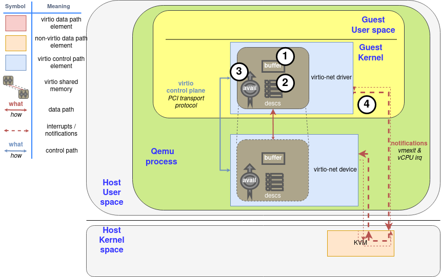
Diagram: Process to make a buffer available

The avail ring must be able to hold the same number of descriptors as the descriptor area, and the descriptor area must have a size power of two, so idx wraps naturally at some point. For example, if the ring size is 256 entries, idx 1 references the same descriptor as idx 257, 513… And it will wrap at a 16 bit boundary. This way, neither side needs to worry about processing an invalid idx: They are all valid.

Avail环必须能够容纳与描述符区相同数量的描述符,描述符区的大小必须是2的幂,所以idx在某一点上自然会被包裹起来。例如,如果环的大小是256个条目,idx 1引用的描述符与idx 257、513…相同。而它将在16位边界处被包裹起来。这样一来,双方都不需要担心处理无效的idx。它们都是有效的。

Note that descriptors can be added in any order to the avail ring, one does not need to start from descriptor table entry 0 nor continue by the next descriptor.

请注意,描述符可以以任何顺序添加到利用环中,不需要从描述符表的第0条开始,也不需要从下一个描述符继续。

Chained descriptors: Supplying large data to the device

The driver can also chain more than one descriptor using its next member. If the NEXT (0x1) flag of a descriptor is set, the data continue in another buffer, making a chain of descriptors. Note that the descriptors in a chain do not share flags: Some descriptors can be read-only, and the others can be write-only. In this case, write-only descriptors must come after all write-only ones.

驱动程序也可以使用其下一个成员来连锁一个以上的描述符。如果一个描述符的NEXT(0x1)标志被设置,数据在另一个缓冲区中继续,形成一个描述符链。注意,一个链中的描述符不共享标志。有些描述符可以是只读的,而其他描述符可以是只写的。在这种情况下,只写的描述符必须排在所有只写的描述符之后。

For example, if the driver has sent us two buffers in a chain with descriptor table indexes 0 and 1 as first operation, the device would see the scenario in Figure 3, and it would be the step 2 again.

例如,如果驱动程序在描述符表索引为0和1的链中向我们发送了两个缓冲区,作为第一次操作,设备会看到图3中的情景,它将再次成为步骤2。

Figure 3: Device sees chained buffers

Used ring: When the device is done with the data

The device employs the used ring to return the used (read or written) buffers to the driver. As the avail ring, it has the flags and idx members. They have the same layout and serve the same purpose, although the notification flag is now called VIRTQ_USED_F_NO_NOTIFY.

设备使用使用过的环将使用过的(读或写)缓冲区返回给驱动。与avail环一样,它也有flags和idx成员。它们具有相同的布局和相同的目的,尽管通知标志现在被称为VIRTQ_USED_F_NO_NOTIFY

After them, it maintains an array of used descriptors. In this array, the device returns not only the descriptor index but also the used length in case of writing.

1
2
3
4
5
6
7
8
9
10
11
12
struct virtq_used {
le16 flags;
le16 idx;
struct virtq_used_elem ring[ /* Queue Size */];
};

struct virtq_used_elem {
/* Index of start of used descriptor chain. */
le32 id;
/* Total length of the descriptor chain which was used (written to) */
le32 len;
};

Listing: Used virtqueue layout

在它们之后,它维护一个已使用的描述符数组。在这个数组中,设备不仅返回描述符的索引,而且在写入的情况下返回已使用的长度。

In case of returning a chain of descriptors, only the id of the head of the chain is returned, and the total written length through all descriptors, not increasing it when data is read. The descriptor table is not touched at all, it is read-only for the device. This is step 5 in the “Process to make a buffer as used” diagram.

在返回描述符链的情况下,只返回链头的id,以及通过所有描述符的总写入长度,在读取数据时不增加它。描述符表完全不被触及,它对设备来说是只读的。这是 “制作使用的缓冲区的过程 “图中的第5步。

For example, if the device uses the chain of descriptors exposed in the Chained descriptors version:

例如,如果设备使用链式描述符版本中暴露的链式描述符:

Figure 4: Device returns buffer chain
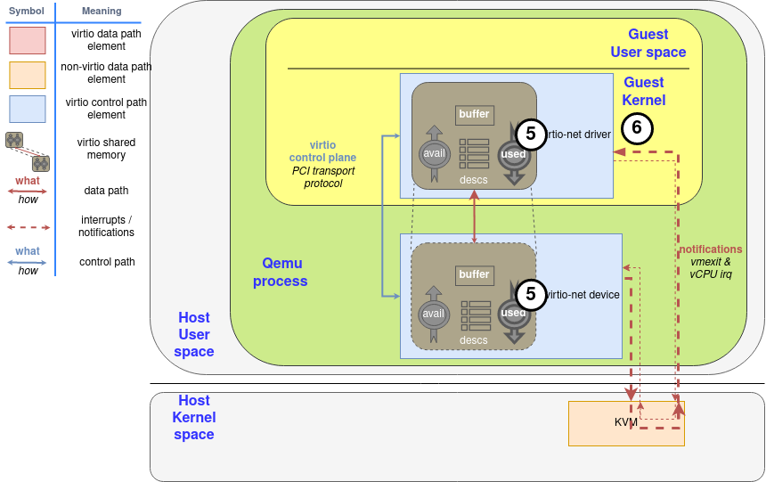
Diagram: Process to mark a buffer as used

Lastly, the device will notify the driver if it sees that the driver wants to be notified, using the used queue flags to know it (step 6).

最后,如果设备看到驱动想被通知,它将通知驱动,使用使用的队列标志来知道它(步骤6)。

Indirect descriptors: supplying a lot of data to the device

Indirect descriptors are a way to dispatch a larger number of descriptors in a batch, increasing the ring capacity. The driver stores a table of indirect descriptors (the same layout as the regular descriptors) anywhere in memory, and inserts a descriptor in the virtqueue with the flag VIRTQ_DESC_F_INDIRECT (0x4) set. The descriptor’s address and length correspond to the indirect table’s ones.

间接描述符是一种在一个批次中调度更多描述符的方法,增加了环的容量。驱动程序在内存的任何地方存储一个间接描述符表(与普通描述符的布局相同),并在virtqueue中插入一个描述符,并设置标志VIRTQ_DESC_F_INDIRECT(0x4)。该描述符的地址和长度对应于间接表的长度。

If we want to add the chain described in section Chained descriptors to an indirect table, the driver first allocates the memory region of 2 entries (32 bytes) to hold the latter (step 2 in the diagram after allocate the buffers in the step 1):

Buffer Len Flags Next
0x8000 0x2000 W|N 1
0xD000 0x2000 W

Figure 4: Indirect table for indirect descriptors

如果我们想在一个间接表上添加链式描述符,驱动程序首先分配2个条目(32字节)的内存区域来容纳后者(图中的第2步,在第1步中分配了缓冲区之后)。

Let’s suppose it has been allocated on memory position 0x2000, and it is the first descriptor made available. As usual, the first step is to include it in the Descriptor area (step 3 in the diagram), so it would look like:

Descriptor Area
Buffer Len Flags Next
0x2000 32 I

Figure 5: Add indirect table to Descriptor area

让我们假设它被分配在内存位置0x2000,并且是第一个可用的描述符。像往常一样,第一步是把它纳入描述符区域(图中的第3步),所以它看起来像。

After that, the steps are the same as with regular descriptors: The driver adds the index of the descriptor marked with the flag in the descriptor area to the avail ring (#0 in this case, step 4 in the diagram), and notify the device as usual (step 5).

之后,步骤与普通描述符相同。驱动程序将描述符区域中标有标志的描述符的索引添加到利用环中(本例中为#0,图中第4步),并像往常一样通知设备(第5步)。
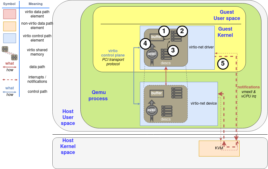
Diagram: Driver make available indirect descriptors

For the device to use its data, and would use the same memory addresses to return its 0x3000 bytes (all 0x8000-0x9FFF and 0xD000-0xDFFF) (Step 6 and 7, same as with regular descriptors). Once used by the device, the driver can release the indirect memory or do whatever it wants with it, as it could do with any regular buffer.

对于设备使用其数据,并将使用相同的内存地址来返回其0x3000字节(所有0x8000-0x9FFF和0xD000-0xDFFF)(步骤6和7,与常规描述符相同)。一旦被设备使用,驱动程序可以释放间接内存或对其做任何事情,就像它可以对任何常规缓冲区做的那样。
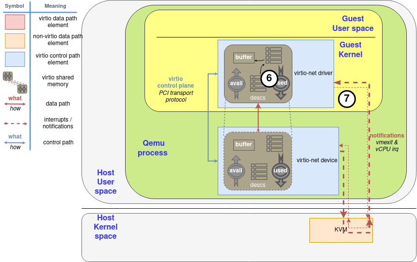
Diagram: Device mark the indirect descriptor as used

Descriptors with INDIRECT flag cannot have NEXT or WRITE flags set, so you cannot chain indirect descriptors in the descriptor table, and the indirect table can contain at maximum the same number of descriptors as the descriptor table.

带有INDIRECT标志的描述符不能设置NEXT或WRITE标志,所以不能在描述符表中连锁间接描述符,间接表最多可以包含与描述符表相同数量的描述符。

Notifications. Learning the “do not disturb” mode

In many systems used and available buffer notifications involve significant overhead. To mitigate it, each virtring maintains a flag to indicate when it wants to be notified. Remember that the driver’s one is read-only by the device, and the device’s one is read-only by the driver.

在许多系统中,使用的和可用的缓冲区通知涉及大量的开销。为了减轻它,每个virtring都维护着一个标志,以表明它什么时候想被通知。记住,驱动的那个是设备只读的,而设备的那个是驱动只读的。

We already know all of this, and its use is pretty straightforward. The only thing you need to take care of is the asynchronous nature of this method: The side of the communication that disables or enables it can’t be sure that the other end is going to know the change, so you can miss notifications or to have more than expected.

我们已经知道了这些,它的使用是非常直接的。你唯一需要注意的是这个方法的异步性。通信中禁用或启用它的一方不能确定另一端是否会知道这个变化,所以你可能会错过通知或要比预期的多。

A more effective way of notifications toggle is enabled if the VIRTIO_F_EVENT_IDX feature bit is negotiated by device and driver: Instead of disable them in a binary fashion, driver and device can specify how far the other can progress before a notification is required using an specific descriptor id. This id is advertised using a extra le16 member at the end of the structure, so they grow like this:

如果设备和驱动协商VIRTIO_F_EVENT_IDX特性位,就可以启用一种更有效的通知切换方式。而不是以二进制的方式禁用它们,驱动和设备可以使用一个特定的描述符id来指定对方在需要通知之前可以进展到什么程度。这个id在结构的末尾使用一个额外的le16成员进行宣传,所以它们的增长方式是这样的。

The struct layout is:

1
2
3
4
5
6
struct virtq_avail {              struct virtq_used {
le16 flags; le16 flags;
le16 idx; le16 idx;
le16 ring[ /* Queue Size */ ]; struct virtq_used_elem ring[Q. size];
le16 used_event; le16 avail_event;
}; };

Listing 3: Event suppression struct notification

This way, every time the driver wants to make available a buffer it needs to check the avail_event on the used ring: If driver’s idx field was equal to avail_event, it’s time to send a notification, ignoring the lower bit of used ring flags member (VIRTQ_USED_F_NO_NOTIFY).

这样一来,每次驱动程序想要提供一个缓冲区时,它需要检查已用环上的avail_event。如果驱动的idx字段等于avail_event,那么就是发送通知的时候了,忽略已用环标志成员的低位(VIRTQ_USED_F_NO_NOTIFY)。

Similarly, if VIRTIO_F_EVENT_IDX has been negotiated, the device will check used_event to know if it needs to send a notification or not. This can be very effective for maintaining a virtqueue of buffers for the device to write, like in the virtio-net device receive queue.

同样,如果VIRTIO_F_EVENT_IDX已经协商好了,设备将检查used_event以知道它是否需要发送通知。这对于维护一个供设备写入的缓冲区的虚拟队列非常有效,就像在virtio-net设备接收队列中一样。

In our next post, we’re going to wrap up and take a look at a number of optimizations on top of both ring layouts which depend on the communication/device type or how each part is implemented.

在我们的下一篇文章中,我们将总结并看看在这两个环形布局之上的一些优化,这些优化取决于通信/设备类型或每个部分的实现方式。
Virtio devices and drivers overview: The headjack and the phone

This three-part series will take you through the main virtio data plane layouts: the split virtqueue and the packed virtqueue. This is the basis for the communication between hosts and virtual environments like guests or containers.

这个由三部分组成的系列,将会带你了解virtio数据平面的布局,split virtuqueue 和 packed virtqueue。这是物理机与虚拟环境比如虚拟机或容器交流的基础。

One of the challenges when coming to explain these approaches is the lack of documentation and the many terms involved. This set of posts attempts to demystify the virtio data plane and provide you with a clear down to earth explanation of what is what.

在解释这些方法时,面临的挑战之一是缺乏文档和涉及的许多术语。这组文章试图揭开virtio数据平面的神秘面纱,并为你提供一个清晰的解释,说明什么是什么。

This is a technical deep dive and is relevant for those who are interested in the bits and bytes of things. It details the communication format between the different virtio parts and data plane protocols.

这是一个技术上的深入研究,与那些对事物的比特和字节感兴趣的人有关。它详细介绍了不同virtio部件和数据平面协议之间的通信格式。

While further extensions, optimizations and features are being added to both virtqueue versions, to improve performance and to simplify implementation, the core of the virtqueue operations remains the same. This is because it has been designed with extensibility in mind.

虽然两个版本的virtqueue都加入了进一步的扩展、优化和功能,以提高性能和简化实现,但virtqueue操作的核心仍然保持不变。这是因为它在设计时就考虑到了可扩展性。

Packed virtqueue, which complements the split virtqueue has been merged in the virtio 1.1 spec, and successfully implemented in both emulated devices (qemu, virtio_net, dpdk) and physical devices.

作为split virtqueue的补充,packed virtqueue已被合并到virtio 1.1规范中,并在模拟设备(qemu、virtio_net、dpdk)和物理设备中成功实现。

We’ll start with an overview of the virtio device, drivers and their data plane interaction. Then we’ll move on to explain the details of the split virtqueue ring layout. This is followed by an overview of the packed ring layout and the advantages it brings over the split virtqueue approach.

我们将首先概述virtio设备、驱动程序和它们的数据平面互动。然后,我们将继续解释split virtqueue ring layout的细节。随后,我们将概述packed ring layout以及它比split virtqueue方法带来的优势。

Virtio devices and drivers overview: who is who

This section provides a brief overview of the virtio devices, virtio drivers, examples of the different architectures you can use and the different components. If you’re already familiar with these topics or you have already followed the virtio networking series you can jump directly to the next section focusing on the virtio rings.

本节简要介绍了virtio设备、virtio驱动、你可以使用的不同架构的例子以及不同的组件。如果你已经熟悉了这些主题,或者你已经关注了virtio网络系列,你可以直接跳到下一节,重点介绍virtio rings。

Virtio devices: In and out the virtual world

A virtio device is a device that exposes a virtio interface for the software to manage and exchange information. It can be exposed to the emulated environment using PCI, Memory Mapping I/O (Just to expose the device in a region of memory) and S/390 Channel I/O. Part of the communication needs to be delegated to theses, like device discovery.

Virtio设备是一个暴露出virtio接口的设备,供软件管理和交换信息。它可以使用PCI、内存映射I/O(只是在内存的一个区域暴露设备)和S/390通道I/O暴露在仿真环境中。部分通信需要委托给这些设备,如设备发现。

Its main task is to convert the signal from the format they have outside of the virtual environment (the VM, the container, etc) to the format they need to be exchanged through the virtio dataplane and vice-versa. This signal could be real (for example the electricity or the light from a NIC) or already virtual (like the representation the host has from a network packet).

它的主要任务是将信号从它们在虚拟环境(虚拟机、容器等)之外的格式转换成它们需要通过virtio数据线交换的格式,反之亦然。这个信号可以是真实的(例如来自网卡的电或光),或者已经是虚拟的(如主机从网络包中得到的表示)。

The virtio interface consist of the following mandatory parts (virtio1.1 spec):

  • Device status field
  • Feature bits
  • Notifications
  • One or more virtqueues

Now we’ll provide additional details to each of these parts and how the device and driver starts communicating using these.

virtio接口由以下强制性部分组成(virtio1.1规范):

  • 设备状态字段
  • 特征位
  • 通知
  • 一个或多个虚拟队列

现在我们将提供这些部分的额外细节,以及设备和驱动如何使用这些部分开始通信。

Device status field: Is everything ok?

The device status field is a sequence of bits the device and the driver use to perform their initialization. We can imagine it as traffic lights on a console, each part set and clear each bit indicating their status.

设备状态字段是设备和驱动程序用来执行其初始化的一个比特序列。我们可以把它想象成控制台上的交通灯,每个部分设置和清除每个位,表示它们的状态。

The guest or the driver set the bit ACKNOWLEDGE (0x1) in the device status field to indicate that it acknowledges the device, and the bit DRIVER (0x2) to indicate an initialization in progress. After that, it starts a feature negotiation using the feature bits (more on this later), and sets bit DRIVER_OK (0x4) and FEATURES_OK (0x8) to acknowledge the features, so communication can start. If the device wants to indicate a fatal failure, it can set bit DEVICE_NEEDS_RESET (0x40), and the driver can do the same with bit FAILED (0x80).

访客或驱动程序在设备状态字段中设置位ACKNOWLEDGE(0x1)以表示它确认了设备,并设置位DRIVER(0x2)以表示初始化正在进行。之后,它开始使用功能位进行功能协商(后面会详细介绍),并设置位DRIVER_OK(0x4)和FEATURES_OK(0x8)来确认功能,这样就可以开始通信了。如果设备想指示一个致命的故障,它可以设置位DEVICE_NEEDS_RESET (0x40),而驱动程序可以用位FAILED (0x80)做同样的事情。

The device communicates the location of these bits using transport specific methods, like PCI scanning or knowing the address for MMIO.

设备使用传输的特定方法来传达这些位的位置,如PCI扫描或知道MMIO的地址。

Feature bits: Setting the communication agreement points

Device’s feature bits are used to communicate what features it supports, and to agree with the drivers about what of them will be used. These can be device-generic or device-specific. As an example of the first case, a bit can acknowledge if the device supports SR-IOV or what memory mode can be used. An example of the second case can be the different offloads it can perform, like checksumming or scatter-gather If the device is a network interface.

设备的功能位用于交流它支持哪些功能,并与驱动程序商定将使用其中哪些功能。这些位可以是设备通用的,也可以是设备特定的。作为第一种情况的一个例子,一个比特可以确认设备是否支持SR-IOV或者可以使用什么内存模式。第二种情况的一个例子是,如果设备是一个网络接口,它可以执行不同的卸载,如校验和或散点收集。

After the device initialization exposed in the previous section, the former reads the feature bits the device offers, and sends back the subset that it can handle. If they agree on them, the driver will allocate and inform about the virtqueues to the device, and all other configuration needed.

在上一节暴露的设备初始化之后,前者会读取设备提供的功能位,并发回它能处理的子集。如果他们达成一致,驱动程序将分配和通知设备的虚拟队列,以及所有其他需要的配置。

Notifications: You have work to do

Devices and drivers must notify that they have information to communicate using a notification. While the semantic of these is specified in the standard, the implementation of these are transport specific, like a PCI interruption or to write to a specific memory location. The device and the driver needs to expose at least one notification method. We will expand on this later in future sections.

设备和驱动程序必须通知他们有使用通知的信息进行通信。虽然这些的语义是在标准中规定的,但这些的实现是特定于传输的,比如PCI中断或写到一个特定的内存位置。设备和驱动程序需要公开至少一个通知方法。我们将在以后的章节中对此进行阐述。

One or more virtqueues: The communication vehicles

A virtqueue is just a queue of guest’s buffers that the host consumes, either reading them or writing to them, and returns to the guest. The current memory layout of a virtqueue implementation is a circular ring, so it is often called the virtring or vring.

They will be the main topic of the next section, Virtqueues and virtio ring, so at this moment is enough with that definition.

virtqueue只是一个guest缓冲区的队列,主机消耗这些缓冲区,要么读取它们,要么写入它们,然后返回给客体。目前virtqueue实现的内存布局是一个圆形的环,所以它通常被称为virtring或vring。

它们将是下一节的主要话题,即virtqueues和virtio ring,所以此刻有了这个定义就足够了。

Virtio drivers: The software avatar

The virtio driver is the software part in the virtual environment that talks with the virtio device using the relevant parts of the virtio spec.

Generally speaking, its virtio control plane tasks are:

  • Look for the device
  • To allocate shared memory in the guest for the communication

Start it using the protocol in Virtio devices.

virtio驱动是虚拟环境中的软件部分,它使用virtio规范的相关部分与virtio设备对话。

一般来说,其virtio控制面的任务是。

  • 寻找设备
  • 在客户中为通信分配共享内存

使用virtio设备中的协议启动它。

Devices and drivers interaction: The scenarios

In this section we are going to locate each virtio networking element (device, driver, and how the communication works) in three different architectures, to provide both a common frame to start explaining the virtio data plane and to show how adaptive it is. We have already presented these elements in past posts, so you can skip this section if you are a virtio-net series reader. On the other hand, if you have not read them, you can use them as a reference to understand this part better.

在这一节中,我们将把每个virtio网络元素(设备、驱动和通信如何工作)放在三个不同的架构中,以提供一个共同的框架来开始解释virtio数据平面,并展示它的适应性。我们已经在过去的文章中介绍了这些元素,所以如果你是virtio-net系列的读者,你可以跳过这一部分。另一方面,如果你没有读过这些文章,你可以把它们作为参考来更好地理解这一部分。

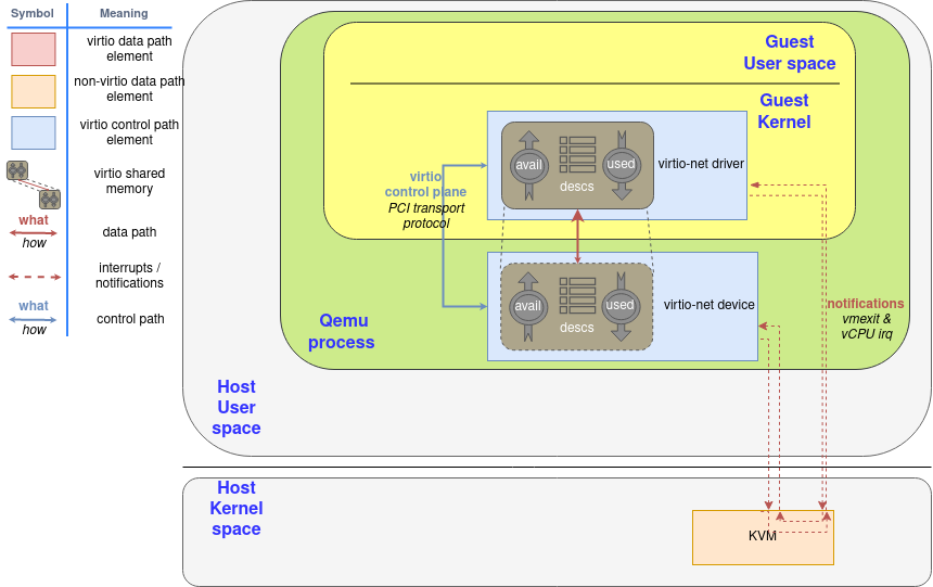
In Introduction to virtio-networking and vhost-net we showed the environment in which qemu created an emulated net device and offered it to the guest’s virtio-net driver. In this environment, the driver notifications are routed from whatever method is exposed to guests (usually, PCI) to KVM interruptions that stop the guest’s processor and return the control to the host (vmexit). Similarly, the device notifications are a special ioctl the host can send to the KVM device (vCPU IRQ). QEMU can access virtqueue information using the shared memory.

在介绍virtio-networking和vhost-net时,我们展示了qemu创建一个模拟的net设备并将其提供给客户的virtio-net驱动程序的环境。在这个环境中,驱动程序的通知从任何暴露给客体的方法(通常是PCI)被路由到KVM中断,停止客体的处理器并将控制权返回给主机(vmexit)。同样地,设备通知是主机可以向KVM设备发送的特殊ioctl(vCPU IRQ)。QEMU可以使用共享内存访问virtqueue信息。

Please note the implications of the virtio rings shared memory concept: The memory the driver and the device access is the same page in RAM, they are not two different regions that follow a protocol to synchronize.

请注意virtio环的共享内存概念的含义。驱动程序和设备访问的内存是RAM中的同一个页面,它们不是两个不同的区域,它们遵循一个协议来进行同步。

Figure 1: Qemu emulated device component diagram

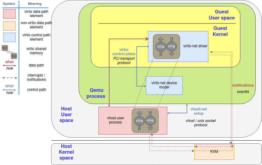
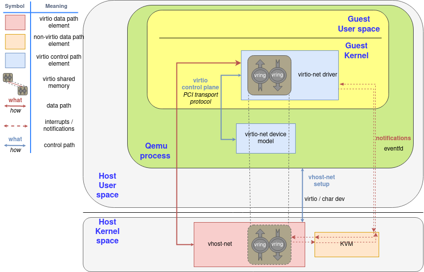
Since the notification now needs to travel from the guest (KVM), to QEMU, and then to the kernel for the latter to forward the network frame, we can spawn a thread in the kernel with access to the guest’s shared memory mapping and then let it handle the virtio dataplane.

由于通知现在需要从guest(KVM)到QEMU,再到内核,以便后者转发网络帧,我们可以在内核中生成一个线程,访问客体的共享内存映射,然后让它处理virtio数据平面。

In that context, QEMU initiates the device using the virtio dataplane, and then forwards the virtio device status to vhost-net, delegating the data plane to it. In this scenario, KVM will use an event file descriptor (eventfd) to communicate the device interruptions, and expose another one to receive CPU interruptions. The guest does not need to be aware of this change, it will operate as the previous scenario.

在这种情况下,QEMU使用virtio数据平面启动设备,然后将virtio设备状态转发给vhost-net,将数据平面委托给它。在这种情况下,KVM将使用一个事件文件描述符(eventfd)来传达设备中断,并公开另一个文件描述符来接收CPU中断。guest不需要意识到这种变化,它将像之前的方案一样操作。

Also, in order to increase the performance, we created an in-kernel virtio-net device (called vhost-net) to offload the data plane directly to the kernel, where packet forwarding takes place:

另外,为了提高性能,我们创建了一个内核内的virtio-net设备(称为vhost-net),将数据平面直接卸载到内核,在那里进行数据包转发。

Figure 2: Virtio-net components diagram

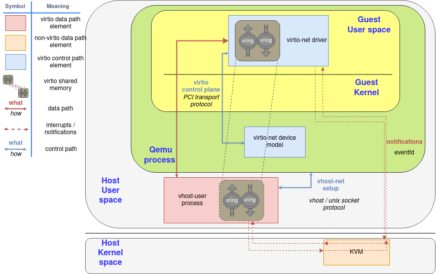
Later on, we moved the virtio device from the kernel to an userspace process in the host (covered in the post “A journey to the vhost-users realm”) that can run a packet forwarding framework like DPDK. The protocol to set all this up is called virtio-user.

后来,我们把virtio设备从内核移到了主机的用户空间进程中(在 “通往vhost-users领域的旅程 “一文中有所涉及),该进程可以运行像DPDK这样的包转发框架。设置这一切的协议被称为virtio-user。

Figure 3: Virtio-user components diagram

It even allows guests to run virtio drivers in guest’s userland, instead of the kernel! In this case, virtio names driver the process that is managing the memory and the virtqueues, not the kernel code that runs in the guest.

它甚至允许客户在客户的用户区运行virtio驱动,而不是在内核中运行 在这种情况下,virtio将驱动程序命名为管理内存和virtqueues的进程,而不是在guest中运行的内核代码

Figure 4: Virtio-user with userland driver in guest

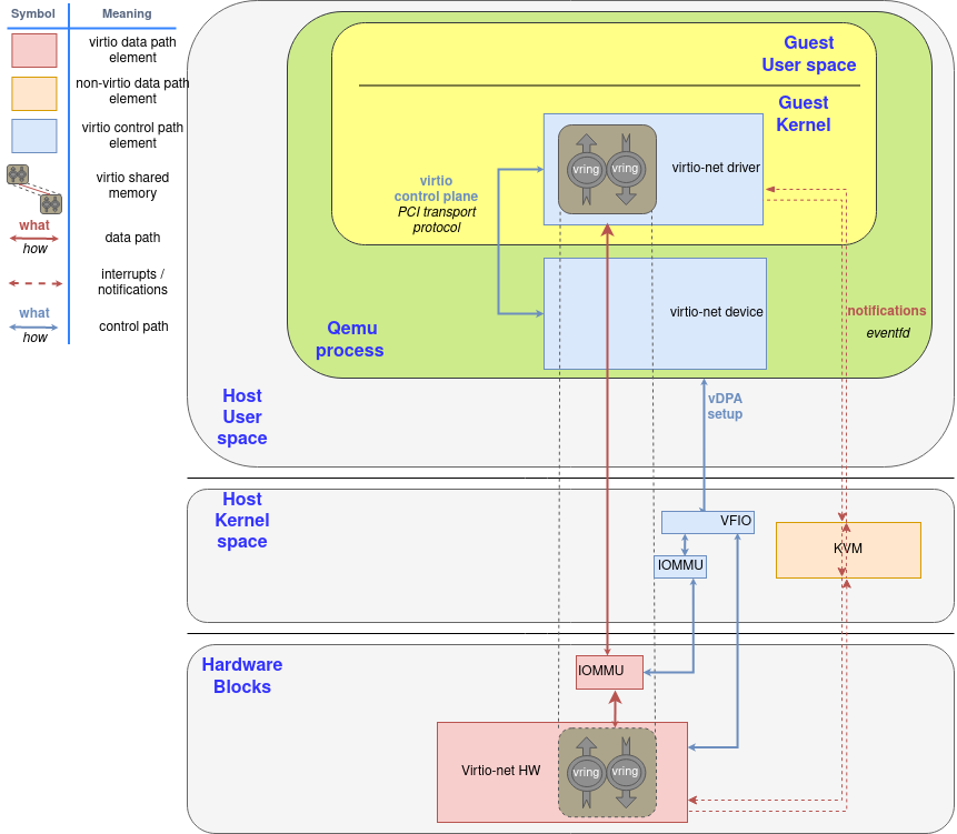
Lastly, we can directly do a virtio device passthrough with the proper hardware. If the NIC supports the virtio data plane, we can expose it directly to the guest with proper hardware (IOMMU device, able to translate between the guest’s and device’s memory addresses) and software (for example, VFIO linux driver, that enables the host to directly give the control of a PCI device to the guest). The device uses the typical hardware signals for notifications infrastructure, like PCI and CPU interruptions (IRQ).

最后,我们可以通过适当的硬件直接进行virtio设备透传。如果网卡支持virtio数据平面,我们可以通过适当的硬件(IOMMU设备,能够在guest和设备的内存地址之间进行转换)和软件(例如,VFIO linux驱动,使主机能够直接将PCI设备的控制权交给guest)将其直接暴露给guest。该设备使用典型的硬件信号来通知基础设施,如PCI和CPU中断(IRQ)。

If a hardware NIC wants to go this way, the easiest approach is to build its driver on top of vDPA, also explained in earlier posts of this series.

如果硬件网卡想走这条路,最简单的方法是在vDPA的基础上构建它的驱动程序,在本系列的早期文章中也有解释.

Figure 5: Virtio hardware passthrough components diagram

We will explain what happens inside of the dataplane communication in the rest of the posts.

我们将在接下来的文章中解释数据平面通信内部发生了什么。

Thanks to the deep investment in standardization, the virtio data plane is the same in whatever way we use across these scenarios, and whatever transport protocol we use. The format of the exchanged messages are the same, and different devices or drivers can negotiate different capabilities or features based on its characteristics using the feature bits, previously mentioned. This way, the virtqueues only act as a common thin layer of device-driver communication that allows to reduce the investment of development and deployment.

由于对标准化的深入投资,virtio数据平面在这些场景中,无论我们使用什么方式,无论我们使用什么传输协议,都是一样的。交换的消息的格式是相同的,不同的设备或驱动程序可以根据它的特点,使用前面提到的特征位,协商不同的能力或特征。这样一来,虚拟队列只是作为设备-驱动程序通信的一个普通薄层,可以减少开发和部署的投资。

As stated on previous blogs on this series, the interest of this standardization is to achieve a slim layer of communication with the virtual environment (instead of emulating a complete piece of hardware), that makes it easier to verify for correctness across different virtualization technologies or hardware.

正如本系列的前几篇博客所述,这种标准化的兴趣在于实现与虚拟环境的薄层通信(而不是模拟一个完整的硬件),这使得在不同的虚拟化技术或硬件之间验证正确性更加容易。

Windows install virtio then reboot met BSOD

Scope

This blog is a practice search about windows virtio driver installation.

Backgroud

For virtualization software, normally guest will install virtio related drivers to get better virtualization performance. But instll virtio driver to windows guest sometimes became complex, so many softwares offer a practice guide about virtio dirver installation

Software practice guide
Proxmox https://pve.proxmox.com/wiki/Windows_VirtIO_Drivers
https://pve.proxmox.com/wiki/Windows_10_guest_best_practices
IBM Cloud orchestrator https://www.ibm.com/docs/en/cloud-orchestrator/2.5.0.3?topic=images-installing-virtio-driver-kvm-hypervisor-only

the guide introduce that how to install virtio driver from win-virtio.iso while lauch windows install.

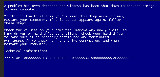
But in practice, if user want install driver to exists guest, windows still get BSOD after virtio driver installed.

So I write this blog to solve related problems.

Newly virtio driver installation

Windows running root disk attached to ide controller and install virtio driver. Then stop guest and move the disk from ide controller to virtio-serial controller, start guest will meet BSOD (no accessible boot device).

This is because windows do not load the virtio controller when install virtio driver to running vm.

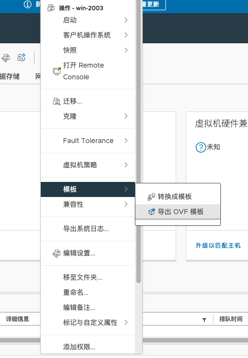
According to P2V practice, how to inject virtio driver to a guest https://portal.nutanix.com/page/documents/kbs/details?targetId=kA00e000000kAWeCAM

we need manually load driver

1
drvload vioser.inf

then install the driver to disk where windows installed:

1
dism /image:c:\ /add-driver /driver:vioscsi.inf

but if you try to do this on a running windows vm, dism will tell you that this operation is not allowed on a running windows. So the kv tell user to do the operation through cmd prompt when windows failed to boot not convinence if there are many guest need do this.

from superuser https://superuser.com/questions/1057959/windows-10-in-kvm-change-boot-disk-to-virtio/1253728#1253728

other solution is raised, the best one is by setting guest into safeboot mode

1
bcdedit /set "{current}" safeboot minimal

windows will load all drivers then change the disk controller seems make sense, but still manually operation is required.

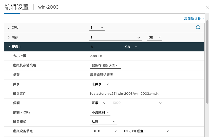
A tricky way is noticed by adding a dummy virtio disk to windows and then install virtio driver, the controller will be loaded at first.

the following steps I followed:

  1. Install the virtio driver in windows
  2. Add a additional “dummy” virtio disk. Reboot and check if the “dummy” works.
  3. If Step 2 works, then switch the boot disk to virtio.
  4. Reboot
  5. Remove the additional “dummy” virtio disk

because we do not need to do more operation inside guest, so this solution can be changed to a automatic way.

And more discussion can be found on reddit:

Looks like you’re having the issue of windows refusing to load the virtio storage drivers at boot.

The only thing I found that works for me is using this method - https://superuser.com/a/1200899. You can also try this method of adding another disk and installing the driver but I personally found that to be very hit and miss.

For the first method you need to use diskpart to assign drive letters to your windows drive and virtio iso this tutorial should help if you don’t know how to do it.

but luckily,

You need to install the virtio drivers on a per storage device basis.

I suggest swapping back to sata and add a empty virtio device to your guest. Then boot and install the virtio driver for the new the device. Last step is to delete the old sata device and mount the device image at the virtio device and boot your guest.

Make sure that libvirt didn’t changed the pcie address of your virtio device as windows registers the driver on a per device basis.

the dummy disk work around can be used because the pci address acutally reused (as the virtio device will be removed and reboot)

This method works well when virtio drivers are newly added, but if you have booted guest with virtio driver installed, change the controller from ide to virtio is complex.

We prefer user to install virtio driver during first windows intallation and make it as a image to avoid controller change.

Virtio driver already installed

While virtio already installed and reboot windows and the disk controller not changed. After reboot the boot disk is still ide.

If you attach virtio-blk disk to guest, it will be recognized and loaded right now.

But if follow the steps below to attach a dummy disk (in this case you attached a virtio-blk disk actually), change the ide controller to virtio will not work, windows kept report BSOD after changed.

Work around is uninstall the virtio driver and reinstall with the steps than reboot every will works.

I think maybe windows only load all drivers which are newly installed. But for existing driver, it only works per disk basis.

Virtio-scsi always works

Cheerfully, if you change the ide/sata controller to virtio-scsi controller after virtio driver installed, windows works well.

More performance test is needed because we kept use virtio-blk for root disk due to some version of virtio driver offered virtio-scsi has bad performance.

Live migration failed due to libvirt keepalive timeout

Live migration is a important part of kvm virtualization at the first day it was designed. However when dive into control plane of libvirt live migration, it became quite complex. So I will describe the basic implementation about it at the early stage.

Libvirt + QEMU basic building blocks

For KVM based virtualization software, normally use libvirt + QEMU to manage guest’s lifecycle. And for live migration we have to know some basic part between libvirt and QEMU.

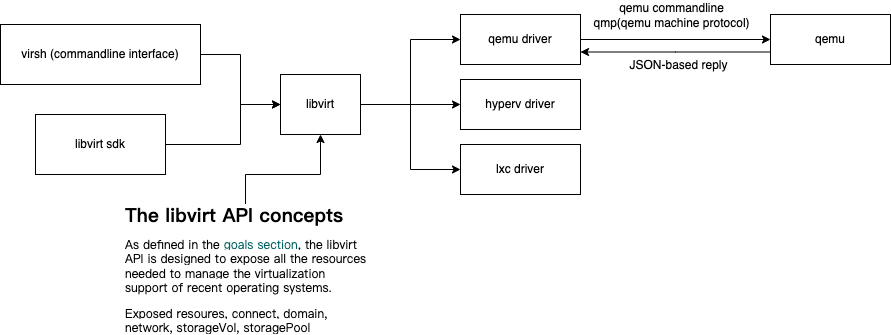
the figure below introduces the basic parts and I just list those parts from left to right:

  • virsh: a commandline interface to management domains
  • libvirt sdk: Python, Go… supported sdk to access libvirt by defined api
  • Libvirt api: exposed connect (the connection to libvirt), domain (guest), network (virtualization network of a hypervisor), storage volume (storage volume as block device which can be used by domain), storage pool (logically used for allocate and store storage volumes)
  • QEMU driver: libvirt driver of qemu, it will translate libvirt api invoke to related qemu operations
  • QEMU: a generic and open source machine emulator and virtualizer
  • qmp: QEMU machine protocol, is a JSON-based protocol, which allows applications to control a QEMU instance

So when we do a live migration operation all those parts will be involved.

Libvirt live migration

For the control plane (libvirt), many concepts need to be introduced before we try to comprehensive its migration logic.

According to https://libvirt.org/migration.html there are two options for network data transport.

  • Native transport: use qemu socket to transport data
    • Require network between hypervisor (firewall issue should be solved)
    • Encryption support is depend on hypervisor
    • Better performance (minimising the number of data copies)
  • Tunnelled transport: the data will be transported through libvirt RPC protocol
    • Encryption supported
    • Less firewall issues
    • Worst performance (due to encryption)

And libvirt also support different control plane, the migration support have common features

  1. a peer2peer flag decide if we use client to connect to libvirtd servers or libvirtd server manage the connection itself
  2. A destination URI with a form like ‘qemu+ssh://desthost/system’ for libvirtd connection
  3. Data transport URI need a optional URI like ‘tcp://10.0.0.1/‘ means use TCP for data transport to hypervisor or libvirtd server
  4. Normally libvirtd on target will automatically determine its native hypervisor URI so is not required in migratin api
  5. If hypervisor do not offer encryption itself, tunnelled migration should be used
  6. When libvirt daemon can not access network use unix migration
  7. For vm with disks on non-shared storage, remember copy all storages

Following are libvirt supported migrations and all available for qemu driver:

  • Native migration, client to two libvirtd servers
  • Native migration, client to and peer2peer between two libvirtd servers
  • Tunnelled migration, client and peer2peer between two libvirtd servers
  • Native migration, client to one libvirtd server
  • Native migration, peer2peer between two libvirtd servers
  • Tunnelled migration, peer2peer between two libvirtd servers
  • Migration using UNIX sockets
  • Migration of VMs using non-shared images for disks

Libvirt keepalive of client

Libvirt use a C/S architecture and during migration libvirt need to support ‘client to two libvirtd servers’ or ‘client to and peer2peer between two libvirtd servers’.

So connection management between client and server or server and server is important for libvirt. And some common conserns for this architecture:

  • Client and server connection
    • Async task not relay on the connection if server implement idempotency
      • Domain object lock help with idempotency
    • Sync task relay on the connection
      • All sync tasks should fail if connection keepalive timeout
  • Server and server connection
    • Source server should be treated as client and same with client and server connection

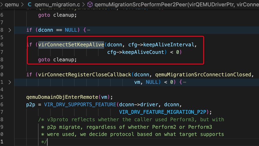
In order to solve basic requirements, libvirt introduced keepalive for client connection. Client can set a keepalive timeout with interval and count (server should support this because a keepalive response is required).

Note:

  • Default settings is configured from libvirtd.conf
  • If set keepalive timeout to 0 means disable keepalive for client

The code from src/rpc/virkeepalive.h is quite easy:

1
2
3
4
5
6
7
8
9
10
11
12
13
14
15
16
17
18
19
20
virKeepAlivePtr virKeepAliveNew(int interval,
unsigned int count,
void *client,
virKeepAliveSendFunc sendCB,
virKeepAliveDeadFunc deadCB,
virKeepAliveFreeFunc freeCB)
ATTRIBUTE_NONNULL(3) ATTRIBUTE_NONNULL(4)
ATTRIBUTE_NONNULL(5) ATTRIBUTE_NONNULL(6);

int virKeepAliveStart(virKeepAlivePtr ka,
int interval,
unsigned int count);
void virKeepAliveStop(virKeepAlivePtr ka);

int virKeepAliveTimeout(virKeepAlivePtr ka);
bool virKeepAliveTrigger(virKeepAlivePtr ka,
virNetMessagePtr *msg);
bool virKeepAliveCheckMessage(virKeepAlivePtr ka,
virNetMessagePtr msg,
virNetMessagePtr *response);

For libvirt keepalive timeout issue

The result from https://bugzilla.redhat.com/show_bug.cgi?id=1367620 butzilla explains a issue of live migration failure due to poor network and the connection between libvirtd servers down which will report a keepalive timeout error.

In libvirtd log (https://libvirt.org/kbase/debuglogs.html) we could see:

1
2
3
4
5
2023-01-05 05:07:36.721+0000: 114785: info : virKeepAliveTimerInternal:131 : RPC_KEEPALIVE_TIMEOUT: ka=0x7f6af4006c60 client=0x7f6af400
6a70 countToDeath=0 idle=30
2023-01-05 05:07:36.721+0000: 114785: debug : virKeepAliveTimerInternal:136 : No response from client 0x7f6af4006a70 after 5 keepalive
messages in 30 seconds
2023-01-05 05:07:36.721+0000: 114785: error : virKeepAliveTimerInternal:138 : internal error: connection closed due to keepalive timeout

And search for client=0x7f6af400 we can find it is a connection created during migration:

the dconn is the URI to destination libvirtd server.

For peer2peer live migration, this issue can be workaround by using seperate network for libvirtd connection and data transport.

Nessus on centos 7

First find download command from official page: https://www.tenable.com/downloads/nessus?loginAttempted=true and I get 10.4.1 rpm with curl command:

1
2
3
curl --request GET \
--url 'https://www.tenable.com/downloads/api/v2/pages/nessus/files/Nessus-10.4.1-es7.x86_64.rpm' \
--output 'Nessus-10.4.1-es7.x86_64.rpm'

and before installation need to disable firewalld and selinux:

1
2
3
4
5
6
7
8
9
systemctl stop firewalld

systemctl disable firewalld

setenforce 0

#set SELINUX=disabled in below file

vim /etc/sysconfig/selinux

then install the rpm:

1
yum localinstall Nessus-10.4.1-es7.x86_64.rpm

and start the service:

1
2
3
systemctl start nessusd

systemctl enable nessusd #Gives error

access nessus through 8443

before active access:

https://www.tenable.com/products/nessus/nessus-essentials to get a activate code and go ahead for your trial of Nessus.

UEFI Windows guest hang after live migration

Notes about debug windows hang issue.

Test case

If qemu guest need to use nvidia GPU, according to https://wiki.archlinux.org/title/PCI_passthrough_via_OVMF#Video_card_driver_virtualisation_detection a workaround need to be setup in domain xml:

1
2
3
4
5
6
7
<features>
...
<kvm>
<hidden state='on'/>
</kvm>
...
</features>

after hidden kvm from guest, the GPU driver could work as expected. But we met an issue with Windows UEFI guest which hidden kvm and hung after live migration.

After searching for google, I got some directions for debug this issue:

  • OVMF live migration issue: OVMF file size changed due to lib upgraded, configuration file length mismatch may cause guest hang
  • Host CPU feature issue: Host CPU features not match, may cause guest paused
  • QEMU/Libvirt issue
  • Windows issue: hidden kvm from guest is not compatible for all windows guest

So I did some test try to figure out which component to suspect:

  • Check OVMF version: not changed
  • Check host CPU feature: not changed
  • Check QEMU/Libvirt log, no virtualization error or error message exists
  • Remove the hidden tag to try live migration: Guest not hang

We can see that kvm hidden seems to blame, but in order to use GPU on UEFI guest this issue should be resolved. So trace what happened during migration is the next step, open following logs for debug usage:

  1. OVMF log by following:

    1
    2
    3
    4
    5
    6
    <qemu:commandline>
    <qemu:arg value='-debugcon'/>
    <qemu:arg value='file:/var/log/libvirt/qemu/debug.log'/>
    <qemu:arg value='-global'/>
    <qemu:arg value='isa-debugcon.iobase=0x402'/>
    </qemu:commandline>
  2. QEMU/libvirt debug, but we already have qemu log under /var/log/libvirt/qemu/

  3. Check windows events after reboot

But before we start debug, the environment related issue should be checked. Because we use nested virtualizatin as default, following environment check tests are required:

  1. Use baremetal host to test
  2. Use latest qemu and libvirt to test
  3. Use latest edk2 to test

While combine test 1 and test 2, we get the result that UEFI wouldn’t hang after live migration. So we decide to test the same scenario on nested environment. And we did not met guest hang issue after upgrade libvirt. Go through the diffs from bug version and upstream:

I found following patch:

1
2
3
4
5
6
7
8
-    if (!loader || !loader->nvram || virFileExists(loader->nvram))
+ if (!loader || !loader->nvram ||
+ (virFileExists(loader->nvram) &&
+ virFileLength(loader->templt, -1) == virFileLength(loader->nvram, -1))
+ )
return 0;

+ unlink(loader->nvram);

which is submitted to solve ovmf upgrade issue:

1
nvram: regenerate nvram mapping file from template when firmware being upgraded

After regenerating nvram mapping, the guest could be successfully migrated. Indeed this discovery solve our problem in short term and I want to get the root cause for why the guest hang and this patch is a important hint.

How ovmf guest perform live migration

How to perform live migration on ovmf guest. I search on edk2.groups.io try to find the answer.

https://edk2.groups.io/g/devel/topic/71141681#55046 and this topic discussed about live migration issue for ovmf guest which is quite helpful.

First of all, topic owner can not perform live migration because OVMF.fd changed its size from 2MB to 4MB which will be checked by qemu and raise length mismatch error like following(I got similar error from my test env):

1
qemu-kvm: Length mismatch: system.flash1: 0x84000 in != 0x20000:Invalid argument

And the reason of extending the flash size is due to https://github.com/tianocore/edk2/commit/b24fca05751f windows HCK require which declared that this is a incompatible change. So the solution may be:

  1. Stick with the same version of the ROM between VMs you want to migrate
  2. Pad your ROM images to some larger size (e.g. 8MB) so that even if they grow a little bigger then you don’t hit the problem.

When think about live migration, all guest’s memory will be migrated to target host, so the memory content of the firmware will be copied to the target host so no matter what loaded at target host memory will be overwritten. So if we want to get rid of this issue, keep the firmware with edk2 version is a good solution.

For legacy guest, BIOS use fixed magic address ranges but UEFI uses dynamically allocated memory, so there is not fixed addresses. When firmware flash image size change, also the content parts will changed too and which can not keep compatible.

But for live migration, due to the memory not changed, the nvram should also not be changed after that. I just quota the answer how ovmf works with live migration:

With live migration, the running guest doesn’t notice anything. This is
a general requirement for live migration (regardless of UEFI or flash).

You are very correct to ask about “skipping” the NVRAM region. With the
approach that OvmfPkg originally supported, live migration would simply
be unfeasible. The “build” utility would produce a single (unified)
OVMF.fd file, which would contain both NVRAM and executable regions, and
the guest’s variable updates would modify the one file that would exist.
This is inappropriate even without considering live migration, because
OVMF binary upgrades (package updates) on the virtualization host would
force guests to lose their private variable stores (NVRAMs).

Therefore, the “build” utility produces “split” files too, in addition
to the unified OVMF.fd file. Namely, OVMF_CODE.fd and OVMF_VARS.fd.
OVMF.fd is simply the concatenation of the latter two.

$ cat OVMF_VARS.fd OVMF_CODE.fd | cmp - OVMF.fd
[prints nothing]

When you define a new domain (VM) on a virtualization host, the domain
definition saves a reference (pathname) to the OVMF_CODE.fd file.
However, the OVMF_VARS.fd file (the variable store template) is not
directly referenced; instead, it is copied into a separate (private)
file for the domain.

Furthermore, once booted, guest has two flash chips, one that maps the
firmware executable OVMF_CODE.fd read-only, and another pflash chip that
maps its private varstore file read-write.

This makes it possible to upgrade OVMF_CODE.fd and OVMF_VARS.fd (via
package upgrades on the virt host) without messing with varstores that
were earlier instantiated from OVMF_VARS.fd. What’s important here is
that the various constants in the new (upgraded) OVMF_CODE.fd file
remain compatible with the old OVMF_VARS.fd structure, across package
upgrades.

If that’s not possible for introducing e.g. a new feature, then the
package upgrade must not overwrite the OVMF_CODE.fd file in place, but
must provide an additional firmware binary. This firmware binary can
then only be used by freshly defined domains (old domains cannot be
switched over). Old domains can be switched over manually – and only if
the sysadmin decides it is OK to lose the current variable store
contents. Then the old varstore file for the domain is deleted
(manually), the domain definition is updated, and then a new (logically
empty, pristine) varstore can be created from the new OVMF_2_VARS.fd
that matches the new OVMF_2_CODE.fd.

During live migration, the “RAM-like” contents of both pflash chips are
migrated (the guest-side view of both chips remains the same, including
the case when the writeable chip happens to be in “programming mode”,
i.e., during a UEFI variable write through the Fault Tolerant Write and
Firmware Volume Block(2) protocols).

Once live migration completes, QEMU dumps the full contents of the
writeable chip to the backing file (on the destination host). Going
forward, flash writes from within the guest are reflected to said
host-side file on-line, just like it happened on the source host before
live migration. If the file backing the r/w pflash chip is on NFS
(shared by both src and dst hosts), then this one-time dumping when the
migration completes is superfluous, but it’s also harmless.

The interesting question is, what happens when you power down the VM on
the destination host (= post migration), and launch it again there, from
zero. In that case, the firmware executable file comes from the
destination host (it was never persistently migrated from the source
host, i.e. never written out on the dst). It simply comes from the OVMF
package that had been installed on the destination host, by the
sysadmin. However, the varstore pflash does reflect the permanent result
of the previous migration. So this is where things can fall apart, if
both firmware binaries (on the src host and on the dst host) don’t agree
about the internal structure of the varstore pflash.

from this long reply, we can get thoes points:

  • Live migration should not be awared by guest
  • Edk2 seperate read-only executable codes and varstore to support firmware upgrade
    • OVMF_CODE.fd keep compitable with orignal version
    • Qemu keep varstores in its nvram which will not be changed
  • For new features if OVMF_CODE.fd can not keep compitable, use another OVMF_CODE_2.fd instead
  • Once live migraiton complete, qemu dump all contents to dest host

So for qemu guest, live migration just migrate memory to dest host and if we keep the same varstore and code with source host, it should be supported. Also because the pflash after live migration is actually in memory, so keep the varstore not changed will keep the compitable (no side-effects during runtime).

And another fact is when we turn off kvm hidden, the migration performs well and no any errors during guest runtime occurs in edk2’s log.

Enable KVM trace

According to: https://www.reddit.com/r/VFIO/comments/80p1q7/high_kvmqemu_cpu_utilization_when_windows_10/ a windows performance topic.

Because there is no abvious log shows any error from qemu or libvirt and it seems that the guest hangs but qemu and libvirt works well, I decide to enable kvm tracing and hope to get more clues.

1
echo 1 > /sys/kernel/debug/tracing/events/kvm/enable

can we can get tracing by:

1
cat /sys/kernel/debug/tracing/trace_pipe

and the following log printed:

1
2
3
4
5
6
7
8
9
10
11
12
13
14
15
16
17
18
19
20
21
<...>-41061 [003] .... 167992.130071: kvm_exit: reason MSR_READ rip 0xfffff8008f9d0c0d info 0 0
<...>-41061 [003] .... 167992.130072: kvm_msr: msr_read 40000020 = 0xdfa1388fd
<...>-41061 [003] d... 167992.130072: kvm_entry: vcpu 0
<...>-41064 [002] .... 167992.130073: kvm_exit: reason MSR_READ rip 0xfffff8008f9d0c0d info 0 0
<...>-41064 [002] .... 167992.130074: kvm_msr: msr_read 40000020 = 0xdfa138912
<...>-41064 [002] d... 167992.130074: kvm_entry: vcpu 3
<...>-41064 [002] .... 167992.130085: kvm_exit: reason MSR_READ rip 0xfffff8008f9d0c0d info 0 0
<...>-41064 [002] .... 167992.130086: kvm_msr: msr_read 40000020 = 0xdfa138988
<...>-41064 [002] d... 167992.130086: kvm_entry: vcpu 3
<...>-41061 [003] .... 167992.130086: kvm_exit: reason MSR_READ rip 0xfffff8008f9d0c0d info 0 0
<...>-41061 [003] .... 167992.130087: kvm_msr: msr_read 40000020 = 0xdfa138998
<...>-41061 [003] d... 167992.130088: kvm_entry: vcpu 0
<...>-41061 [003] .... 167992.130102: kvm_exit: reason MSR_READ rip 0xfffff8008f9d0c0d info 0 0
<...>-41061 [003] .... 167992.130103: kvm_msr: msr_read 40000020 = 0xdfa138a32
<...>-41061 [003] d... 167992.130103: kvm_entry: vcpu 0
<...>-41064 [002] .... 167992.130103: kvm_exit: reason MSR_READ rip 0xfffff8008f9d0c0d info 0 0
<...>-41064 [002] .... 167992.130104: kvm_msr: msr_read 40000020 = 0xdfa138a3f
<...>-41064 [002] d... 167992.130104: kvm_entry: vcpu 3
<...>-41064 [002] .... 167992.130114: kvm_exit: reason MSR_READ rip 0xfffff8008f9d0c0d info 0 0
<...>-41064 [002] .... 167992.130114: kvm_msr: msr_read 40000020 = 0xdfa138aaa
<...>-41064 [002] d... 167992.130115: kvm_entry: vcpu 3

the vcpus seems run kvm_entry and kvm_exit forever to do msr_read and combine with top:

1
2
3
4
5
6
7
8
9
10
11
top - 12:54:08 up 1 day, 22:42,  1 user,  load average: 5.69, 5.82, 6.10
Tasks: 1 total, 0 running, 1 sleeping, 0 stopped, 0 zombie
%Cpu0 : 87.5 us, 12.5 sy, 0.0 ni, 0.0 id, 0.0 wa, 0.0 hi, 0.0 si, 0.0 st
%Cpu1 :100.0 us, 0.0 sy, 0.0 ni, 0.0 id, 0.0 wa, 0.0 hi, 0.0 si, 0.0 st
%Cpu2 :100.0 us, 0.0 sy, 0.0 ni, 0.0 id, 0.0 wa, 0.0 hi, 0.0 si, 0.0 st
%Cpu3 : 87.5 us, 12.5 sy, 0.0 ni, 0.0 id, 0.0 wa, 0.0 hi, 0.0 si, 0.0 st
KiB Mem : 10054364 total, 7086476 free, 2163892 used, 803996 buff/cache
KiB Swap: 0 total, 0 free, 0 used. 7563464 avail Mem

PID USER PR NI VIRT RES SHR S %CPU %MEM TIME+ COMMAND
41029 root 20 0 5193164 1.6g 17104 S 387.5 17.0 394:17.63 qemu-kvm

guest’s sys usage is quite high use perf to get more details about this process:

1
perf kvm --host top -p `pidof qemu-kvm`

I see that:

1
2
3
4
5
6
7
Samples: 99K of event 'cycles', Event count (approx.): 10268746210
Overhead Shared Object Symbol ◆
18.41% [kernel] [k] vmx_vcpu_run ▒
6.43% [kernel] [k] vcpu_enter_guest ▒
5.58% [kernel] [k] pvclock_clocksource_read ▒
3.84% [kernel] [k] mutex_lock ▒
2.79% [kernel] [k] vmx_handle_exit

vmx_vcpu_run is high (on intel cpu) this means cpu switch to guest mode and show that guest mode and kernel mode switch spent a lot of time.

And by kvm tracing we can see many vm entry/exit so check the reason why vm exit happend (because the vcpu mode switch now spend too much time)

1

Just use a small piece of the output:

1
2
3
4
5
6
7
8
9
10
11
12
13
14
15
16
17
18
19
20
21
[root@172-24-195-187 ~]# perf stat -e 'kvm:*' -a -- sleep 1

Performance counter stats for 'system wide':

206,380 kvm:kvm_entry
0 kvm:kvm_hypercall
0 kvm:kvm_hv_hypercall
263 kvm:kvm_pio
0 kvm:kvm_fast_mmio
0 kvm:kvm_cpuid
162 kvm:kvm_apic
206,395 kvm:kvm_exit
0 kvm:kvm_inj_virq
0 kvm:kvm_inj_exception
0 kvm:kvm_page_fault
202,600 kvm:kvm_msr
0 kvm:kvm_cr
195 kvm:kvm_pic_set_irq
81 kvm:kvm_apic_ipi
370 kvm:kvm_apic_accept_irq
65 kvm:kvm_eoi

kvm_msr is the main reason for vm exit and which matches kvm tracing.

By collect kvm events:

1
perf kvm --host stat live

we could see MSR_READ and EXTERNAL_INTERRUPT used almost all of the time.

1
2
3
4
5
6
7
8
9
10
11
12
13
14
13:02:10.174121

Analyze events for all VMs, all VCPUs:

VM-EXIT Samples Samples% Time% Min Time Max Time Avg time

MSR_READ 6022 78.14% 74.10% 0.71us 21778.22us 42.52us ( +- 17.16% )
EXTERNAL_INTERRUPT 1494 19.38% 21.65% 0.53us 12810.58us 50.08us ( +- 29.22% )
IO_INSTRUCTION 126 1.63% 1.16% 23.80us 51.45us 31.73us ( +- 1.56% )
APIC_WRITE 26 0.34% 0.06% 3.23us 10.96us 8.39us ( +- 4.81% )
EOI_INDUCED 20 0.26% 0.02% 1.93us 3.27us 2.63us ( +- 3.21% )
EPT_MISCONFIG 19 0.25% 3.01% 29.30us 9795.61us 548.07us ( +- 93.74% )

Total Samples:7707, Total events handled time:345545.97us.

from kvm tracing:

1
<...>-41064 [000] .... 168733.114930: kvm_msr: msr_read 40000020 = 0xfb3c08a54

we can find 0x40000020 from linux kernel code:

1
2
/* MSR used to read the per-partition time reference counter */
#define HV_X64_MSR_TIME_REF_COUNT 0x40000020

it seems a hyperv clocksource related issue so I just remote the hyperclock field from libvirt xml and the migration issue disappeared after that.

Try to find root cause

Actually we can workaround our issue by remove the clocksource from vm configuration but we do not known the root cause but only a vm_exit and failed to read hyperv clocksource.

So simply trace kernel code for more details.

vmx.h defines lots of EXIT reasons:

1
#define EXIT_REASON_MSR_READ            31

and vmx.c register handlers

1
2
3
4
5
6
7
8
9
/*
* The exit handlers return 1 if the exit was handled fully and guest execution
* may resume. Otherwise they set the kvm_run parameter to indicate what needs
* to be done to userspace and return 0.
*/
static int (*const kvm_vmx_exit_handlers[])(struct kvm_vcpu *vcpu) = {
...
[EXIT_REASON_MSR_READ] = handle_rdmsr,
};

than move to handle_rdmsr

1
2
3
4
5
6
7
8
9
10
11
12
13
14
15
16
17
18
19
20
21
static int handle_rdmsr(struct kvm_vcpu *vcpu)
{
u32 ecx = vcpu->arch.regs[VCPU_REGS_RCX];
struct msr_data msr_info;

msr_info.index = ecx;
msr_info.host_initiated = false;
if (vmx_get_msr(vcpu, &msr_info)) {
trace_kvm_msr_read_ex(ecx);
kvm_inject_gp(vcpu, 0);
return 1;
}

trace_kvm_msr_read(ecx, msr_info.data);

/* FIXME: handling of bits 32:63 of rax, rdx */
vcpu->arch.regs[VCPU_REGS_RAX] = msr_info.data & -1u;
vcpu->arch.regs[VCPU_REGS_RDX] = (msr_info.data >> 32) & -1u;
skip_emulated_instruction(vcpu);
return 1;
}

because we see the trace from kvm that means trace_kvm_msr_read_ex is executed and will return 1 which means vm could resume.

If you look back to the kvm process trace

1
perf kvm --host top -p `pidof qemu-kvm`

we can find the inside vmx_vcpu_run, the vm vmresume is used and according to the code, the function will finished after kvm_inject_gp(vcpu, 0); and vm will entry guest.

1
2
3
4
5
6
7
8
9
10
11
12
13
14
15
16
17
18
19
20
21
22
23
vmx_vcpu_run  /proc/kcore
Percent│ mov 0x238(%rcx),%rbx
│ mov 0x230(%rcx),%rdx
│ mov 0x250(%rcx),%rsi
0.11 │ mov 0x258(%rcx),%rdi
│ mov 0x248(%rcx),%rbp
│ mov 0x260(%rcx),%r8
│ mov 0x268(%rcx),%r9
0.03 │ mov 0x270(%rcx),%r10
│ mov 0x278(%rcx),%r11
│ mov 0x280(%rcx),%r12
│ mov 0x288(%rcx),%r13
0.11 │ mov 0x290(%rcx),%r14
0.02 │ mov 0x298(%rcx),%r15
│ mov 0x228(%rcx),%rcx
│ ↓ jne 2a1
│ vmlaunch
│ ↓ jmp 2a4
0.02 │2a1: vmresume
45.46 │2a4: mov %rcx,0x8(%rsp)
4.07 │ pop %rcx
1.50 │ mov %rax,0x220(%rcx)
2.07 │ mov %rbx,0x238(%rcx)

So that means guest will exit due to its own READ_MSR requirement.

Check kernel related code, the function chains are following:

1
vmx_get_msr -> kvm_get_msr_common -> kvm_hv_get_msr_common

look into kvm_hv_get_msr_common

1
2
3
4
5
6
7
8
9
10
11
12
int kvm_hv_get_msr_common(struct kvm_vcpu *vcpu, u32 msr, u64 *pdata, bool host)
{
if (kvm_hv_msr_partition_wide(msr)) {
int r;

mutex_lock(&vcpu->kvm->arch.hyperv.hv_lock);
r = kvm_hv_get_msr_pw(vcpu, msr, pdata);
mutex_unlock(&vcpu->kvm->arch.hyperv.hv_lock);
return r;
} else
return kvm_hv_get_msr(vcpu, msr, pdata, host);
}

because msr count matches:

1
2
3
4
5
6
7
8
9
10
11
12
13
14
15
16
17
18
static bool kvm_hv_msr_partition_wide(u32 msr)
{
bool r = false;

switch (msr) {
case HV_X64_MSR_GUEST_OS_ID:
case HV_X64_MSR_HYPERCALL:
case HV_X64_MSR_REFERENCE_TSC:
case HV_X64_MSR_TIME_REF_COUNT:
case HV_X64_MSR_CRASH_CTL:
case HV_X64_MSR_CRASH_P0 ... HV_X64_MSR_CRASH_P4:
case HV_X64_MSR_RESET:
r = true;
break;
}

return r;
}

so the read fall into kvm_hv_get_msr_pw

1
2
3
4
5
case HV_X64_MSR_TIME_REF_COUNT:
/* read-only, but still ignore it if host-initiated */
if (!host)
return 1;
break;

and finally return 1 or report

1
2
3
vcpu_unimpl(vcpu, "Hyper-V uhandled wrmsr: 0x%x data 0x%llx\n",
msr, data);
return 1;

come to here it seems a guest bug and according to: https://msrc-blog.microsoft.com/2018/12/10/first-steps-in-hyper-v-research/ we can get some information about EXIT_REASON_MSR_READ

that

1
Hyper-V handles MSR access (both read and write) in its VMEXIT loop handler. It’s easy to see it in IDA: it’s a large switch case over all the MSRs supported values, with the default case of falling back to rdmsr/wrmsr, if that MSR doesn’t have special treatment by the hypervisor. Note that there are authentication checks in the MSR read/write handlers, checking the current partition permissions. From there we can find the different MSRs Hyper-V supports, and the functions to handle read and write.

So it seems a Hyper-V feature to access the MSR timeout ref count.

Check qemu doc about ‘Hyper-V Enlightenments’, it explains the usage:

1
2
hv-time
Enables two Hyper-V-specific clocksources available to the guest: MSR-based Hyper-V clocksource (HV_X64_MSR_TIME_REF_COUNT, 0x40000020) and Reference TSC page (enabled via MSR HV_X64_MSR_REFERENCE_TSC, 0x40000021). Both clocksources are per-guest, Reference TSC page clocksource allows for exit-less time stamp readings. Using this enlightenment leads to significant speedup of all timestamp related operations.

and used for speedup of all timestamp related operations but in this case the guest do not response as a result.

And come to here, I noticed that when guest migrated, some lines come into qemu.log

1
2
3
4
2022-11-16T09:53:19.529516Z qemu-kvm: warning: TSC frequency mismatch between VM (2095020 kHz) and host (2095087 kHz), and TSC scaling unavailable
2022-11-16T09:53:19.533393Z qemu-kvm: warning: TSC frequency mismatch between VM (2095020 kHz) and host (2095087 kHz), and TSC scaling unavailable
2022-11-16T09:53:19.533626Z qemu-kvm: warning: TSC frequency mismatch between VM (2095020 kHz) and host (2095087 kHz), and TSC scaling unavailable
2022-11-16T09:53:19.533816Z qemu-kvm: warning: TSC frequency mismatch between VM (2095020 kHz) and host (2095087 kHz), and TSC scaling unavailable

qemu-kvm warning TSC frequency mismatched which normally not occurs for guest.

When check kernel code, we can see that:

1
2
3
4
5
6
7
8
9
10
11
12
13
14
15
16
17
18
19
20
21
22
23
24
25
26
27
28
29
30
31
static int kvm_arch_set_tsc_khz(CPUState *cs)
{
X86CPU *cpu = X86_CPU(cs);
CPUX86State *env = &cpu->env;
int r;

if (!env->tsc_khz) {
return 0;
}

r = kvm_check_extension(cs->kvm_state, KVM_CAP_TSC_CONTROL) ?
kvm_vcpu_ioctl(cs, KVM_SET_TSC_KHZ, env->tsc_khz) :
-ENOTSUP;
if (r < 0) {
/* When KVM_SET_TSC_KHZ fails, it's an error only if the current
* TSC frequency doesn't match the one we want.
*/
int cur_freq = kvm_check_extension(cs->kvm_state, KVM_CAP_GET_TSC_KHZ) ?
kvm_vcpu_ioctl(cs, KVM_GET_TSC_KHZ) :
-ENOTSUP;
if (cur_freq <= 0 || cur_freq != env->tsc_khz) {
warn_report("TSC frequency mismatch between "
"VM (%" PRId64 " kHz) and host (%d kHz), "
"and TSC scaling unavailable",
env->tsc_khz, cur_freq);
return r;
}
}

return 0;
}

qemu tries to KVM_SET_TSC_KHZ but failed will show thoes lines.

From hypervisor functional specification:

1
The TscScale value is used to adjust the Virtual TSC value across migration events to mitigate TSC frequency changes from one platform to another.

used to cut down the mitigate TSC frequency change for guest.

So look for qemu code:

1
2
3
4
5
6
7
8
if (level == KVM_PUT_FULL_STATE) {
/* We don't check for kvm_arch_set_tsc_khz() errors here,
* because TSC frequency mismatch shouldn't abort migration,
* unless the user explicitly asked for a more strict TSC
* setting (e.g. using an explicit "tsc-freq" option).
*/
kvm_arch_set_tsc_khz(cpu);
}

during live migration, this trace will be printed but do not abort migration.

Indeed, newer nvidia driver do not require kvm hidden: https://www.heiko-sieger.info/passing-through-a-nvidia-rtx-2070-super-gpu/ so the concerns about the use case maybe not necessary.

I write a mail to community to discuss if there is any better way to solve the problem.

https://lists.nongnu.org/archive/html/qemu-discuss/2022-11/msg00028.html

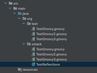
Plugable system in practice 00

Introduction

This blog used to introduce a practice of plugin system implementation of zstack.

I will finish base of plugin load, metadate definition, capability negotiation and usage part of Java. And following section describe abstractions of this implementation.

Abstractions

I make some abstractions to satisfy our aim.

  • Unique identifer to find plugin and execute it
  • Capability negotiation and version information
  • Observer pattern to keep all modules use same way access plugin

PluginInterface

Plugin capability currently defines SUPPORTED and UNSUPPORTED for plugin definition

1
2
3
4
public enum PluginCapabilityState {
SUPPORTED,
UNSUPPORTED
}

Define a plugin interface including three methods:

1
2
3
4
5
6
7
public interface PluginInterface {
String pluginUniqueName();

String version();

Map<String, PluginCapabilityState> capabilities();
}

note: capabilities offer a map about custom plugin and expected use enum value

use reflection to collect interfaces extend this interface as the metadata of all kinds of plugins:

1
2
3
public interface PluginEndpointSender extends PluginInterface {
boolean send(PluginEndpointData message);
}

so we need a manage class as the factory of plugin

PluginManager

1
2
3
4
5
public interface PluginManager {
boolean isCapabilitySupported(String pluginName, String capability);

<T extends PluginInterface> T getPlugin(Class<? extends PluginInterface> pluginClass);
}

this class defines two methods, first one used to report plugin capability and another one return singleton plugin.

And in order to reduce complexity, only scan interfaces under abstraction module as meta interfaces

1
2
3
4
5
6
7
8
9
10
11
12
13
Platform.getReflections().getSubTypesOf(PluginInterface.class).forEach(clz -> {
if (!clz.getCanonicalName().contains("org.zstack.abstraction")
|| !clz.isInterface()) {
return;
}

if (interfaceMetadata.contains(clz)) {
throw new CloudRuntimeException(
String.format("duplicate PluginProtocol[name: %s]", clz));
}

interfaceMetadata.add(clz);
});

then load plugin instances from meta class:

1
2
3
4
5
6
7
8
9
10
11
12
13
14
15
16
17
18
interfaceMetadata.forEach(clz -> Platform.getReflections().getSubTypesOf(clz)
.forEach(pluginInstanceClz -> {
try {
PluginInterface pluginInterface = pluginInstanceClz.getConstructor().newInstance();
if (pluginInstances.containsKey(pluginInterface.pluginUniqueName())) {
throw new CloudRuntimeException(String.format("duplicate plugin[class: %s]",
pluginInstanceClz));
}

pluginInstances.put(pluginInstanceClz, pluginInterface);
logger.debug(String.format("load plugin: %s, name: %s, capabilities: \n %s",
pluginInterface.version(),
pluginInterface.pluginUniqueName(),
JSONObjectUtil.toJsonString(pluginInterface.capabilities())));
} catch (Exception e) {
throw new CloudRuntimeException(e);
}
}));

class will be used as the key and instance singleton will be stored and ready to use.

Use getPlugin could get the singleton. But currently version and uniqueName do not have specific usage but capabilties could be used to check if the plugin support the feature.

Version is used to check pluginInterface’s compatibility if pluginInterface has any uncompatible change, old version of plugin can run under compatible mode or just rejects load the plugin.

And now all plugins implemented pluginInterface will be loaded and not security check which should be done in pluginInterface and I will design it in next blogs.

Conclusion

Now I implemented part of loading the plugin, for usage is quite easy because developer only need to store the plugin class name as a variable to access the plugin but current safety issue is still should cared by all modules use plugin manager. So in next blog, I will do more works to resolve security requirements.

JVM loaded classes rapidly increased issue

Rapidly increased JVM loaded classes

When debug a oom issue on new version of application. I noticed that

Old version:

New version:

The classes increased almost twice compare to the old version.

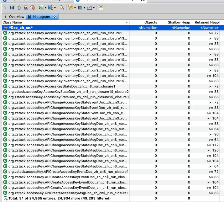
So I just export loaded classes to figure out what classes increased at first.

After a compare, we got a obvious increased class:

for the new version

about 25000 Doc classes is loaded and 45439 + 25000 = 70439 seems very near to 74.3k.

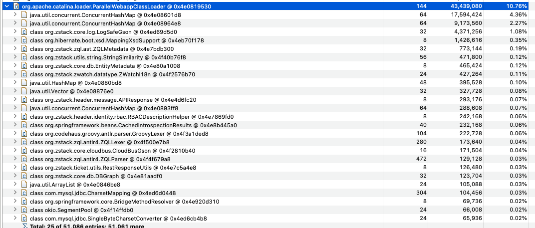
So check the heap dump by Dominator tree, by comparing heap usage, one class come into view is that:

Code reading

ZStack use reflections to get information and offer framework level capabilities.

1
2
3
public static Reflections reflections = new Reflections(ClasspathHelper.forPackage("org.zstack"),
new SubTypesScanner(), new MethodAnnotationsScanner(), new FieldAnnotationsScanner(),
new TypeAnnotationsScanner(), new MethodParameterScanner());

for reflections-0.9.10

1
2
3
4
5
6
7
8
9
10
11
12
13
14
15
16
17
18
19
20
21
22
23
24
25
26
27
protected void scan(URL url) {
Vfs.Dir dir = Vfs.fromURL(url);

try {
for (final Vfs.File file : dir.getFiles()) {
// scan if inputs filter accepts file relative path or fqn
Predicate<String> inputsFilter = configuration.getInputsFilter();
String path = file.getRelativePath();
String fqn = path.replace('/', '.');
if (inputsFilter == null || inputsFilter.apply(path) || inputsFilter.apply(fqn)) {
Object classObject = null;
for (Scanner scanner : configuration.getScanners()) {
try {
if (scanner.acceptsInput(path) || scanner.acceptResult(fqn)) {
classObject = scanner.scan(file, classObject);
}
} catch (Exception e) {
if (log != null && log.isDebugEnabled())
log.debug("could not scan file " + file.getRelativePath() + " in url " + url.toExternalForm() + " with scanner " + scanner.getClass().getSimpleName(), e.getMessage());
}
}
}
}
} finally {
dir.close();
}
}

with a groovy closure org.zstack.sso.header.APICreateCasClientEventDoc_zh_cn$_run_closure1

this part of code executed will skip filter and goes throught all scanners with their acceptsInput and acceptResult directly

refer to ZStack used Scanner, following code will be used:

FieldAnnotationsScanner

1
2
3
4
5
6
7
8
9
10
11
12
13
14
15
16
public class FieldAnnotationsScanner extends AbstractScanner {
public void scan(final Object cls) {
final String className = getMetadataAdapter().getClassName(cls);
List<Object> fields = getMetadataAdapter().getFields(cls);
for (final Object field : fields) {
List<String> fieldAnnotations = getMetadataAdapter().getFieldAnnotationNames(field);
for (String fieldAnnotation : fieldAnnotations) {

if (acceptResult(fieldAnnotation)) {
String fieldName = getMetadataAdapter().getFieldName(field);
getStore().put(fieldAnnotation, String.format("%s.%s", className, fieldName));
}
}
}
}
}

SubTypeScanner

1
2
3
4
5
6
7
8
9
10
11
12
13
14
15
16
17
18
19
20
21
22
23
24
25
26
27
28
29
30
31
public class SubTypesScanner extends AbstractScanner {

/** created new SubTypesScanner. will exclude direct Object subtypes */
public SubTypesScanner() {
this(true); //exclude direct Object subtypes by default
}

/** created new SubTypesScanner.
* @param excludeObjectClass if false, include direct {@link Object} subtypes in results. */
public SubTypesScanner(boolean excludeObjectClass) {
if (excludeObjectClass) {
filterResultsBy(new FilterBuilder().exclude(Object.class.getName())); //exclude direct Object subtypes
}
}

@SuppressWarnings({"unchecked"})
public void scan(final Object cls) {
String className = getMetadataAdapter().getClassName(cls);
String superclass = getMetadataAdapter().getSuperclassName(cls);

if (acceptResult(superclass)) {
getStore().put(superclass, className);
}

for (String anInterface : (List<String>) getMetadataAdapter().getInterfacesNames(cls)) {
if (acceptResult(anInterface)) {
getStore().put(anInterface, className);
}
}
}
}

MethodAnnotationsScanner

1
2
3
4
5
6
7
8
9
10
11
public class MethodAnnotationsScanner extends AbstractScanner {
public void scan(final Object cls) {
for (Object method : getMetadataAdapter().getMethods(cls)) {
for (String methodAnnotation : (List<String>) getMetadataAdapter().getMethodAnnotationNames(method)) {
if (acceptResult(methodAnnotation)) {
getStore().put(methodAnnotation, getMetadataAdapter().getMethodFullKey(cls, method));
}
}
}
}
}

TypeAnnotationsScanner

1
2
3
4
5
6
7
8
9
10
11
12
13
14
public class TypeAnnotationsScanner extends AbstractScanner {
public void scan(final Object cls) {
final String className = getMetadataAdapter().getClassName(cls);

for (String annotationType : (List<String>) getMetadataAdapter().getClassAnnotationNames(cls)) {

if (acceptResult(annotationType) ||
annotationType.equals(Inherited.class.getName())) { //as an exception, accept Inherited as well
getStore().put(annotationType, className);
}
}
}

}

MethodParameterScanner

1
2
3
4
5
6
7
8
9
10
11
12
13
14
15
16
17
18
19
20
21
22
23
24
25
26
27
28
29
public class MethodParameterScanner extends AbstractScanner {

@Override
public void scan(Object cls) {
final MetadataAdapter md = getMetadataAdapter();

for (Object method : md.getMethods(cls)) {

String signature = md.getParameterNames(method).toString();
if (acceptResult(signature)) {
getStore().put(signature, md.getMethodFullKey(cls, method));
}

String returnTypeName = md.getReturnTypeName(method);
if (acceptResult(returnTypeName)) {
getStore().put(returnTypeName, md.getMethodFullKey(cls, method));
}

List<String> parameterNames = md.getParameterNames(method);
for (int i = 0; i < parameterNames.size(); i++) {
for (Object paramAnnotation : md.getParameterAnnotationNames(method, i)) {
if (acceptResult((String) paramAnnotation)) {
getStore().put((String) paramAnnotation, md.getMethodFullKey(cls, method));
}
}
}
}
}
}

All of them only offer scan and not extra processes were defined.

Check abount their acceptsInput() and acceptResult() methods from AbstractScanner:

1
2
3
4
5
6
7
 public boolean acceptsInput(String file) {
return getMetadataAdapter().acceptsInput(file);
}

public boolean acceptResult(final String fqn) {
return fqn != null && resultFilter.apply(fqn);
}

acceptResult will be used by SubTypesScanner

1
2
3
4
5
public SubTypesScanner(boolean excludeObjectClass) {
if (excludeObjectClass) {
filterResultsBy(new FilterBuilder().exclude(Object.class.getName())); //exclude direct Object subtypes
}
}

to reject direct Object subtypes

and acceptsInput use metadataAdapter(JavassistAdapter.java),check if file end with .class

so for reflections-0.9.10 if groovy closure file exists will .class suffix and not extend object directly, will be loaded by reflection.

After upgrade to reflections-0.10.2

1
2
3
4
5
6
7
8
9
10
11
12
13
14
15
16
17
18
19
20
21
22
23
24
25
26
27
28
29
(configuration.isParallel() ? urls.stream().parallel() : urls.stream()).forEach(url -> {
Vfs.Dir dir = null;
try {
dir = Vfs.fromURL(url);
for (Vfs.File file : dir.getFiles()) {
if (doFilter(file, configuration.getInputsFilter())) {
ClassFile classFile = null;
for (Scanner scanner : configuration.getScanners()) {
try {
if (doFilter(file, scanner::acceptsInput)) {
List<Map.Entry<String, String>> entries = scanner.scan(file);
if (entries == null) {
if (classFile == null) classFile = getClassFile(file);
entries = scanner.scan(classFile);
}
if (entries != null) collect.get(scanner.index()).addAll(entries);
}
} catch (Exception e) {
if (log != null) log.trace("could not scan file {} with scanner {}", file.getRelativePath(), scanner.getClass().getSimpleName(), e);
}
}
}
}
} catch (Exception e) {
if (log != null) log.warn("could not create Vfs.Dir from url. ignoring the exception and continuing", e);
} finally {
if (dir != null) dir.close();
}
});

code of scan changed to new version and scanners moved to enum

1
2
3
4
5
6
7
8
9
10
11
12
13
14
15
16
17
18
19
20
21
22
23
24
25
26
27
28
29
30
31
32
33
34
35
36
37
38
39
40
41
42
43
44
45
46
47
48
49
50
51
52
53
54
55
56
57
58
59
60
public enum Scanners implements Scanner, QueryBuilder, NameHelper {

/** scan type superclasses and interfaces
* <p></p>
* <i>Note that {@code Object} class is excluded by default, in order to reduce store size.
* <br>Use {@link #filterResultsBy(Predicate)} to change, for example {@code SubTypes.filterResultsBy(c -> true)}</i>
* */
SubTypes {
/* Object class is excluded by default from subtypes indexing */
{ filterResultsBy(new FilterBuilder().excludePattern("java\\.lang\\.Object")); }

@Override
public void scan(ClassFile classFile, List<Map.Entry<String, String>> entries) {
entries.add(entry(classFile.getSuperclass(), classFile.getName()));
entries.addAll(entries(Arrays.asList(classFile.getInterfaces()), classFile.getName()));
}
},

/** scan method annotations */
MethodsAnnotated {
@Override
public void scan(ClassFile classFile, List<Map.Entry<String, String>> entries) {
getMethods(classFile).forEach(method ->
entries.addAll(entries(getAnnotations(method::getAttribute), methodName(classFile, method))));
}
},

/** scan field annotations */
FieldsAnnotated {
@Override
public void scan(ClassFile classFile, List<Map.Entry<String, String>> entries) {
classFile.getFields().forEach(field ->
entries.addAll(entries(getAnnotations(field::getAttribute), fieldName(classFile, field))));
}
},

/** scan type annotations */
TypesAnnotated {
@Override
public boolean acceptResult(String annotation) {
return super.acceptResult(annotation) || annotation.equals(Inherited.class.getName());
}

@Override
public void scan(ClassFile classFile, List<Map.Entry<String, String>> entries) {
entries.addAll(entries(getAnnotations(classFile::getAttribute), classFile.getName()));
}
},

/** scan method parameters types and annotations */
MethodsParameter {
@Override
public void scan(ClassFile classFile, List<Map.Entry<String, String>> entries) {
getMethods(classFile).forEach(method -> {
String value = methodName(classFile, method);
entries.addAll(entries(getParameters(method), value));
getParametersAnnotations(method).forEach(annotations -> entries.addAll(entries(annotations, value)));
});
}
},

almost same logic is supported but check details about the scan() method

1
2
3
4
5
6
7
8
9
10
11
12
13
14
for (Scanner scanner : configuration.getScanners()) {
try {
if (doFilter(file, scanner::acceptsInput)) {
List<Map.Entry<String, String>> entries = scanner.scan(file);
if (entries == null) {
if (classFile == null) classFile = getClassFile(file);
entries = scanner.scan(classFile);
}
if (entries != null) collect.get(scanner.index()).addAll(entries);
}
} catch (Exception e) {
if (log != null) log.trace("could not scan file {} with scanner {}", file.getRelativePath(), scanner.getClass().getSimpleName(), e);
}
}

acceptsInput will be used to do filter which check file end with .class suffix but filterResultsBy is not executed only if entries = scanner.scan(classFile) is used.

So when List<Map.Entry<String, String>> entries = scanner.scan(file); return entries the result won’t be exclude.

Hands-on test

I set up a maven project to test reflections issue with a project:

and main code:

1
2
3
4
5
6
7
8
9
10
11
12
13
14
15
16
17
18
19
20
21
22
23
24
25
26
27
28
29
30
31
32
33
34
35
36
37
38
39
40
41
42
43
44
package org.zstack;

import org.reflections.Reflections;
import org.reflections.scanners.*;
import org.reflections.util.ClasspathHelper;

import java.io.IOException;
import java.lang.management.ManagementFactory;
import java.util.Set;

public class TestReflections {
public static void main(String[] args) throws IOException {
System.out.println("==========================");
printLoadedClasses(null);
System.out.println("==========================");


// reflections 0.9.10
Reflections reflections = new Reflections(ClasspathHelper.forPackage("org.zstack"),
new SubTypesScanner(false), new MethodAnnotationsScanner(), new FieldAnnotationsScanner(),
new TypeAnnotationsScanner(), new MethodParameterScanner());

// reflections 0.10.2
// Reflections reflections = new Reflections(ClasspathHelper.forPackage("org.zstack"),
// new SubTypesScanner(false), new MethodAnnotationsScanner(), new FieldAnnotationsScanner(),
// new TypeAnnotationsScanner(), new MethodParameterScanner());

System.out.println("==========================");
printLoadedClasses(reflections);
System.out.println("==========================");
}

private static void printLoadedClasses(Reflections reflections) throws IOException {
if (reflections != null) {
Set<String> types = reflections.getAllTypes();

types.forEach(System.out::println);

System.out.println("loaded class number from reflection: " + types.size());
}

System.out.println("loaded class number from jmx: " + ManagementFactory.getClassLoadingMXBean().getLoadedClassCount());
}
}

finally the output of reflections 0.10.2:

1
2
3
4
5
6
7
8
9
10
11
12
13
14
15
16
17
18
19
20
21
22
23
24
25
26
27
28
29
30
31
groovy.lang.GroovyObject
java.lang.Cloneable
org.codehaus.groovy.runtime.GeneratedClosure
groovy.lang.GroovyObjectSupport
groovy.lang.Closure
java.util.concurrent.Callable
java.lang.Object
groovy.lang.GroovyCallable
groovy.lang.Script
java.lang.Runnable
java.io.Serializable
org.test.TestGroovy2$_run_closure1
org.zstack.TestGroovy2$_run_closure1
org.test.TestGroovy$_run_closure1
org.zstack.TestGroovy$_run_closure1$_closure2
org.zstack.TestGroovy$_run_closure1
org.zstack.TestGroovy3$_run_closure1$_closure2
org.test.TestGroovy$_run_closure1$_closure2
org.test.TestGroovy3$_run_closure1$_closure2
org.test.TestGroovy3$_run_closure1
org.test.TestGroovy2$_run_closure1$_closure2
org.zstack.TestGroovy2$_run_closure1$_closure2
org.zstack.TestGroovy3$_run_closure1
org.zstack.TestReflections
org.test.TestGroovy2
org.test.TestGroovy3
org.zstack.TestGroovy
org.test.TestGroovy
org.zstack.TestGroovy2
org.zstack.TestGroovy3
loaded class number from reflection: 30

and the reflection 0.10.9:

1
2
org.zstack.TestReflections
loaded class number from reflection: 1

we can found out that even a specified reflection from class path org.zstack unrelated class still appears.

So I just goolge the reflection issue, it come out directly:

https://github.com/ronmamo/reflections/issues/373

we can solve this issue by adding some workaround

1
2
3
4
5
6
7
8
9
10
11
// reflections 0.10.2
ConfigurationBuilder builder = ConfigurationBuilder.build()
.setUrls(ClasspathHelper.forPackage("org.zstack"))
.setScanners(new SubTypesScanner(false),
new MethodAnnotationsScanner(),
new FieldAnnotationsScanner(),
new TypeAnnotationsScanner(),
new MethodParameterScanner())
.setExpandSuperTypes(false)
.filterInputsBy(new FilterBuilder().includePackage("org.zstack"));
Reflections reflections = new Reflections(builder);

Where is root cause

But after a solve the problem by add some hack for reflections, I still want to known what is the root cause.

So I check the code again try to find out what happened.

Compare scanners between 0.10.2 and 0.9.10

1
2
3
4
5
6
7
8
9
10
11
12
13
14
15
16
17
18
19
20
// SubTypes
// reflections 0.10.2
entries.add(this.entry(classFile.getSuperclass(), classFile.getName()));
entries.addAll(this.entries(Arrays.asList(classFile.getInterfaces()), classFile.getName()));

// reflections 0.9.10
filterResultsBy(new FilterBuilder().exclude(Object.class.getName())); //exclude direct Object subtypes

String className = getMetadataAdapter().getClassName(cls);
String superclass = getMetadataAdapter().getSuperclassName(cls);

if (acceptResult(superclass)) {
getStore().put(superclass, className);
}

for (String anInterface : (List<String>) getMetadataAdapter().getInterfacesNames(cls)) {
if (acceptResult(anInterface)) {
getStore().put(anInterface, className);
}
}

0.9.10 will filter the superclass before put it into reflections store but 0.10.2 use it directly.

in 0.9.10 scan works like following:

1
2
3
4
5
6
7
8
9
10
11
12
13
if (inputsFilter == null || inputsFilter.apply(path) || inputsFilter.apply(fqn)) {
Object classObject = null;
for (Scanner scanner : configuration.getScanners()) {
try {
if (scanner.acceptsInput(path) || scanner.acceptResult(fqn)) {
classObject = scanner.scan(file, classObject);
}
} catch (Exception e) {
if (log != null && log.isDebugEnabled())
log.debug("could not scan file " + file.getRelativePath() + " in url " + url.toExternalForm() + " with scanner " + scanner.getClass().getSimpleName(), e.getMessage());
}
}
}

scanner will check fqn of class first and then check the interface but in 0.10.2 version:

1
2
3
4
5
6
7
8
9
10
11
12
13
14
for (Scanner scanner : configuration.getScanners()) {
try {
if (doFilter(file, scanner::acceptsInput)) {
List<Map.Entry<String, String>> entries = scanner.scan(file);
if (entries == null) {
if (classFile == null) classFile = getClassFile(file);
entries = scanner.scan(classFile);
}
if (entries != null) collect.get(scanner.index()).addAll(entries);
}
} catch (Exception e) {
if (log != null) log.trace("could not scan file {} with scanner {}", file.getRelativePath(), scanner.getClass().getSimpleName(), e);
}
}

File will be checked before scan by Filter but superclass’s belonging is not checked which seems to blame.

But actually, groovy closure does not extend Object but GroovyObject, so reflections will still load groovy closures. So check reflections getAllTypes()

for 0.9.10

1
2
3
4
5
6
7
8
public Set<String> getAllTypes() {
Set<String> allTypes = Sets.newHashSet(store.getAll(index(SubTypesScanner.class), Object.class.getName()));
if (allTypes.isEmpty()) {
throw new ReflectionsException("Couldn't find subtypes of Object. " +
"Make sure SubTypesScanner initialized to include Object class - new SubTypesScanner(false)");
}
return allTypes;
}

for 0.10.2

1
2
3
4
public Set<String> getAll(Scanner scanner) {
Map<String, Set<String>> map = store.getOrDefault(scanner.index(), Collections.emptyMap());
return Stream.concat(map.keySet().stream(), map.values().stream().flatMap(Collection::stream)).collect(Collectors.toCollection(LinkedHashSet::new));
}

All most same but in 0.9.10 Object related types will be returned. So as a result, only java objects is returned.

Work around on 0.10.2 can use following codes:

1
2
3
4
5
6
7
8
9
10
ConfigurationBuilder builder = ConfigurationBuilder.build()
.setUrls(ClasspathHelper.forPackage("org.zstack"))
.setScanners(new SubTypesScanner(false),
new MethodAnnotationsScanner(),
new FieldAnnotationsScanner(),
new TypeAnnotationsScanner(),
new MethodParameterScanner())
.setExpandSuperTypes(false)
.filterInputsBy(new FilterBuilder().includePackage("org.zstack"));
Reflections reflections = new Reflections(builder);

filterInputsBy will filter class not in package org.zstack and setExpandSuperTypes will ignore super types of scanned result.

Note: but the result still contains groovy closure even its count cut down to acceptable numbers.

Windows 2003 vmware v2v hands-on

When use virt-v2v to convert vm from vmware to kvm, windows guest sometimes meet issue after start on kvm. For quite old windows os version, typically windows 2003, may meet following blue screen issue:

with code 0x0000007B.

So I write a hands-on blog to help fix this issue.

When search for this error on vmware kb or MSDN, we can find out that, wrong driver is the main reason cause this problem.

Usually, it’s recommanded to do following check for the v2v vm:

  1. Confirm the vm running well on original host, if its already error check configuration first.
  2. Check if virt-v2v failed to install virtio driver to guest during virt-v2v convert.
  3. Check kvm configuration, that root disk use ide to keep compitable.
  4. Check if windows disabled driver installatin by its group policy.

Besides those issues, if you migrate a windows 2003 with cd-rom you will also met this blue screen issue. Due to windows will change device order after v2v and root disk not work as expected.

So I write this practical blog to resolve device changed issue on windows 2003 v2v.

  1. Uninstall vmware guest tools and drivers (avoid failed to install driver issue)

  2. Change the disk controller to ide and reboot guest

  3. Attach MergeIde.iso to guest

    the iso contains a .reg and a .bat file. Run the .reg first and run the .bat. The device will be recorded and prepare for hypervisor change.

  4. export ovf template or use virt-v2v to export the vm the kvm.

  5. check the vm started without blue screen.

For windows, it seems that with cd-rom or disk order changed guest, after hypervisor migration, windows can not identify the original order of thoes devices due to hardware change. So record the device seems a easy solution for v2v case.

Note: this solution is also useful for Windows XP v2v

Download MergeIDE.iso from: https://www.virtualbox.org/wiki/Migrate_Windows

Refer to Microsoft commands: https://learn.microsoft.com/en-US/troubleshoot/windows-client/performance/stop-error-7b-or-inaccessible-boot-device-troubleshooting

Plugable module architecture design and thoughts about its implementation

Introduction

Software’s complexity grows as time goes by which is suitable to describe ZStack now. Quantities of features has been integrated in the past years and developers suffered on customizing features for some commercial reasons which pushed us to think about how to get rid of customizing feature efforts and focus on core function to earn more technical advantages.

Generallly, customizing features is harmful when compared to normal features (but maybe it can get commercial benifits so do not take this as absolute rule), because more customers use normal features.

But because some integration requests already designed which not only require maintainance but also need development for new integration. For example, a feature for security is desing to use third-part machine to do encryption,but when customer use the feature, they all use different machine which caused lots of development cost for us to do the integrations.

In these cases, a plugable architecture is required to cut down the cost and this is the reason to write this blog to record related design and make it a repeatable practice.

Requirements

For existing systems which need to support multi types of resources, typically use a register way to connect the management layer and application layers. And the application layers use a couple of standard interfaces to keep consistency and seperate implementation from mechanism.

So for the aim of delveloping a plugable module architecture if we still follows the pattern, easily we will be distrubed by the change of core codes from the mechanism. For example, if the core changes the mechanism as a result, application should change all of the interfaces as expected, so development is required which is not satisfied with out target.

Just after that small think, list all requirements before starting design. Following points are the aim of this architecture:

  • Low development efforts or configuration as a service.
  • No core code dependency. Any changes to mechanism should be avoid.
  • Security. Plugin module should not cause any security issue.

Base on those points, the architecture should be changed to expose its mechanism by interfaces.

For example

  1. read plugin configuration and verify it
  2. generate code proxy according to the configuration
  3. limited db access controled by the code proxy
  4. Invokations can be verified by unit test to check the plugin can work as expected
  5. change the configuration the refresh it could update the code proxy
  6. plugin configurations use a specified syntax
  7. if code proxy support runtime refresh can be configured

From writing configurations, functional features can be easily supported.

If any requests need data structure support, a configuration map shoud be support for more customize and in this way we can easily create a http client to support some modules.

But if customize feature use any third-part libs, only configuration is not enough to support.

For code level, maybe open source interfaces is still needed.

We should offer read only data structure and functional interfaces but should not involve core codes of Java which in most cases, are aspectj support, spring containers and so on. Only pure java should be used for all plugin modules.

In next section, we will raise examples of two module, one is not suitable for plugable module and other one is suitable for plugable.

Login module

Multiple login methods should be supported because many standard third-part authentication is already exists for example, CAS, oauth2, ldap and so on.

If you already have a customized system for authentication, I seems diffcult to integrate another system with existing one. Because the authentication actually need to transfer sensitive information to do authenticate but which is not safe enough to expose those data for plugin exactly.

From the usage of CAS, oauth2 we can see a generally authentication service just redirect authentication to itself and returns a authentication result and finally redirect to the right page. So sensitive information do not transferred but use a token to verify client’s response instead.

For ldap, just access its database directly to verify if the user is exists and finish authentication. Because ldap just integrated with ZStack so also no data transferred but ldap module itself need to care about the security issue which already resolve by third-part libs.

So when we tries to support plugin for login, password or any key liked information need to be exposed which is quite unsafe and have potential security risks. Compared to ldap verification, password is used directly and also faces the same problem.

For login module integration, two ways are recommended. One is using open-source authentication like CAS or oauth2. Another is integrating ZStack API to use account/user directly.

Following figure shows the flows of login module

  • Support plugable system, main auth or additinal auth should be exposed
  • Sensitive information go through the whole flow
  • CAS and oauth2 use their own authentication which is not related the current architecture

Alarm/Event system

For alarm event system, only expose monitor messages which seems more suitable to be developed as a plugable system.

When have lots of endpoint support, some use stantard libs like dingtalk and microsoft teams, offers api for message sending. But when sms system require integration, this became diffcult due to the lack of stantard apis.

So a plugable system can be powerful to reduce development efforts.

For example, sms systems all have their own apis the usages, so the interation of api is the first step. But actually the business scenarios are not only limited on send message. Maybe message distribution strategy is required, and message format is required.

So seperate those parts as followings:

  • Send sms message
  • Distribution strategy
  • Message format
  • ….

When design plugable system, the most important thing is that we should seperate mechanism requirements and strategy requirements.

For message format, actually, all kinds of message required this feature and can be noted as general feature and mechanism and we can also call it customize message format. The format change do not influence how the message send or comsumed.

Distribution strategy, from the name, we can known that no specific rules or format could be announced because the strategy always changes from one the another.

Send sms message. also the integration part but the message with a format is what we can offered and only how to send the message should be defined and which is I think can be seperated from the system.

And more informations maybe, endpoint type, status and those ZStack defined fields also need to be involved in the plugable system so we get a architecture like following:

A plugable endpoint in designed to manage endpoint plugins and plugin should obey following rules:

  • Offer endpoint type
  • Implement interface to send message
  • Unit test for endpoint plugin

And the design of plugable endpoint may like following:

So plugable endpoint should define a interface require type and send() method’s implementation for the usage. Take the interface to a seperate open source package and publish to maven repository, its easy for develop and easy to use. By reflections, endpoint could be initialized from jar so just add jar to your dependency directory is ok.

To develop a plugin for new sns endpoint no need to known the logic or usage of orignal application system but developer could focus on the send method itself.

On the other hand, application level should extend orignal CURD api to suitable for those plugin definition and keep compitable with other endpoints.

TODO

  • Database access is not limited which should add limited on database service itself.
  • Rules for all kind of plugins so that plugins can be managed together and distribution can keep consistency
  • More examples
  • For exsiting modules, try to refactor the plugin types to get rid of module dependency