This post continues where the “Virtio devices and drivers overview“ leaves off. After we have explained the scenario in the previous post, we are reaching the main point: how does the data travel from the virtio-device to the driver and back?
这篇文章继续 “Virtio设备和驱动概述 “的内容。在上一篇文章中,我们已经解释了这个场景,我们即将到达重点:数据如何从virtio设备到驱动,然后再返回?
Buffers and notifications: The work routine
As stated earlier, a virtqueue is just a queue of guest’s buffers that the host consumes, either reading them or writing to them. A buffer can be read-only or write-only from the device point of view, but never both.
如前所述,virtqueue只是一个guest的缓冲区队列,主机消耗它们,要么读取它们,要么写入它们。从设备的角度来看,一个缓冲区可以是只读的,也可以是只写的,但绝不是两者都是。
The descriptors can be chained, and the framing of the message can be spread whatever way is more convenient. For example, to spread a 2000 byte message in one single buffer or to use two 1000 byte buffers should be the same.
描述符可以是链状的,消息的构架可以以任何更方便的方式传播。例如,将2000字节的信息分散在一个单一的缓冲区中,或使用两个1000字节的缓冲区,应该是一样的。
Also, it provides driver to device notifications (doorbell) method, to signal that one or more buffers have been added to the queue, and vice-versa, devices can interrupt the driver to signal used buffers. It is up to the underlying driver to provide the right method to dispatch the actual notification, for example using PCI interruptions or memory writing: The virtqueue only standardizes the semantics of it.
另外,它还提供了驱动程序到设备的通知(门铃)方法,以信号显示一个或多个缓冲区已被添加到队列中,反之亦然,设备可以中断驱动程序以信号显示已使用的缓冲区。这取决于底层驱动程序提供正确的方法来调度实际的通知,例如使用PCI中断或内存写入。virtqueue只是对它的语义进行了标准化。
As stated before, the driver and the device can advise the other to not to emit notifications to reduce its dispatching overhead. Since this operation is asynchronous we will describe how to do so in further sections.
如前所述,驱动和设备可以建议对方不要发出通知,以减少其调度开销。由于这个操作是异步的,我们将在后续章节中描述如何做到这一点。
Split virtqueue: the beauty of simplicity
The split virtqueue format separates the virtqueue into three areas, where each area is writable by either the driver or the device, but not both:
- Descriptor Area: used for describing buffers.
- Driver Area: data supplied by driver to the device. Also called avail virtqueue.
- Device Area: data supplied by device to driver. Also called used virtqueue.
split virtqueue格式将virtqueue分成三个区域,每个区域都可以被驱动或设备写入,但不能同时写入。
- 描述符区:用于描述缓冲区。
- 驱动区:由驱动提供给设备的数据。也称为利用虚拟队列。
- 设备区:由设备提供给驱动的数据。也称为used virtqueue。
They need to be allocated in the driver’s memory for it to be able to access them in a straightforward way. Buffer addresses are stored from the driver’s point of view, and the device needs to perform an address translation. There are many ways for the device to access it depending on the latter nature:
- For an emulated device in the hypervisor (like qemu), the guest’s address is in its own process memory.
- For other emulated devices like vhost-net or vhost-user, a memory mapping needs to be done, like POSIX shared memory. A file descriptor to that memory is shared through vhost protocol.
- For a real device a hardware-level translation needs to be done, usually via IOMMU.
它们需要被分配到驱动程序的内存中,以便它能够直接访问它们。缓冲区地址从驱动程序的角度存储,设备需要进行地址转换。根据后者的性质,设备有很多方法可以访问它。
- 对于管理程序中的仿真设备(如qemu),客户的地址在它自己的进程内存中。
- 对于其他仿真设备,如vhost-net或vhost-user,需要做一个内存映射,像POSIX共享内存一样。该内存的文件描述符是通过vhost协议共享的。
- 对于一个真实的设备,需要做一个硬件级的转换,通常是通过IOMMU。
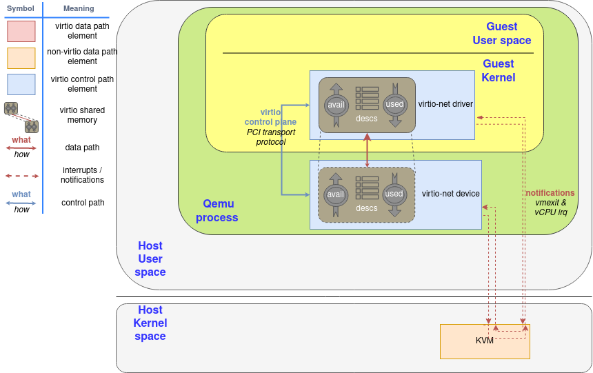
Shared memory with split ring elements
Descriptor ring: Where is my data?
The descriptor area (or descriptor ring) is the first one that needs to be understood. It contains an array of a number of guest addressed buffers and its length. Each descriptor also contains a set of flags indicating more information about it. For example, the buffer continues in another descriptor buffer if the 0x1 bit is set, and the buffer is write-only for the device if the bit 0x2 is set, and is read-only if it is clear.
描述符区(或描述符环)是第一个需要被理解的。它包含一个由若干客体寻址的缓冲区和其长度组成的数组。每个描述符还包含一组标志,表示关于它的更多信息。例如,如果0x1位被设置,缓冲区在另一个描述符缓冲区中继续,如果0x2位被设置,缓冲区对设备来说是只写的,如果它被清除,则是只读的。
This is the layout of a single descriptor. We will call leN for N bits in little endian format.
2
3
4
5
6
le64 addr;
le32 len;
le16 flags;
le16 next; // Will explain this one later in the section "Chained descriptors"
};Listing: Split Virtqueue descriptor layout
这是一个单一描述符的布局。我们将调用leN来表示little endian格式的N位。
Avail ring: Supplying data to the device
The next interesting structure is the driver area, or avail ring. Is the room where the driver places the descriptor (indexes) the device is going to consume. Note that placing a buffer here doesn’t mean that the device needs to consume immediately: virtio-net, for example, provides a bunch of descriptors for packet receiving that are only used by the device when a packet arrives, and are “ready to consume” until that moment.
下一个有趣的结构是驱动区,或者说Avail环。是驱动程序放置设备要消耗的描述符(索引)的空间。注意,在这里放置缓冲区并不意味着设备需要立即消费:例如,virtio-net为数据包接收提供了一堆描述符,这些描述符只有在数据包到达时才会被设备使用,直到那一刻才会 “准备消费”。
The avail ring has two important fields that only the driver can write and the device only can read them: idx and flags. The idx field indicates where the driver would put the next descriptor entry in the avail ring (modulo the queue size). On the other hand, the least significant bit of flags indicates if the driver wants to be notified or not (called
VIRTQ_AVAIL_F_NO_INTERRUPT).
avail环有两个重要的字段,只有驱动程序可以写入,设备只能读取它们:idx和flags。idx字段指出了驱动程序将把下一个描述符条目放在avail ring中的位置(modulo the queue size)。另一方面,flags的最小有效位表示驱动是否要被通知(称为VIRTQ_AVAIL_F_NO_INTERRUPT)。
After these two fields, an array of integers of the same length as the descriptors ring. So the avail virtqueue layout is:
2
3
4
5
le16 flags;
le16 idx;
le16 ring[ /* Queue Size */ ];
};Listing: Avail virtqueue layout
在这两个字段之后,是一个与描述符环相同长度的整数阵列。因此,avail virtqueue layout:
Figure 1 shows a descriptor table with a 2000 bytes long buffer that starts in position 0x8000, and an avail ring that still does not have any entry. After all the steps, a components diagram highlighting the descriptor area update. The first step for the driver is to allocate the buffer with the memory and fill it (this is the step 1 in the “Process to make a buffer available” diagram), and to make available on the descriptor area after that (step 2).
图1显示了一个具有2000字节长的缓冲区的描述符表,它从位置0x8000开始,而一个利用环仍然没有任何条目。在所有的步骤之后,一个组件图突出了描述符被更新的部分。驱动程序的第一步是分配缓冲区的内存并将其填满(这是 “使缓冲区可用的过程 “图中的第1步),然后在描述符区上使其可用(第2步)。
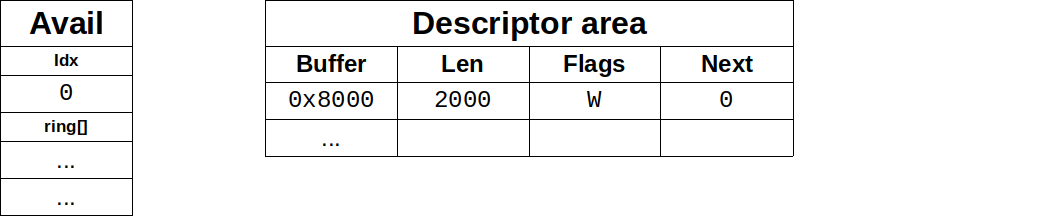
Figure 1: Driver writes a buffer in descriptor ring
After populating descriptor entry, driver advises of it using the avail ring: It writes the descriptor index #0 in the first entry of the avail ring, and updates idx entry accordly. The result of this is shown in Figure 2. In the case that supply chained buffers, only the descriptor head index should be added this way, and avail idx would increase only by 1. This is the step 3 in the diagram.
在填充完描述符条目后,驱动通知它使用空闲环。它将描述符的索引#0写在avail ring的第一个条目中,并相应地更新idx条目。其结果如图2所示。在提供链式缓冲区的情况下,只有描述符头部的索引应该这样添加,而avail idx只增加1。这就是图中的第三步。
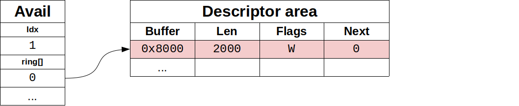
Figure 2: Driver offers the buffer with avail ring
From now on, the driver should not modify the available descriptor or the exposed buffer at any moment: It is under the device’s control. Now the driver needs to notify the device if the latter has enabled notifications at that moment (more on how the device manages this later). This is the last step 4 in the diagram.
从现在开始,驱动程序不应该在任何时候修改可用的描述符或暴露的缓冲区。这是由设备控制的。现在,驱动程序需要通知设备,如果后者在当时启用了通知功能(后面会有更多关于设备如何管理的内容)。这就是图中的最后一步4。
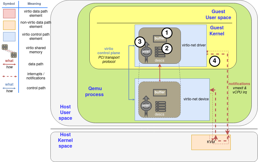
Diagram: Process to make a buffer available
The avail ring must be able to hold the same number of descriptors as the descriptor area, and the descriptor area must have a size power of two, so idx wraps naturally at some point. For example, if the ring size is 256 entries, idx 1 references the same descriptor as idx 257, 513… And it will wrap at a 16 bit boundary. This way, neither side needs to worry about processing an invalid idx: They are all valid.
Avail环必须能够容纳与描述符区相同数量的描述符,描述符区的大小必须是2的幂,所以idx在某一点上自然会被包裹起来。例如,如果环的大小是256个条目,idx 1引用的描述符与idx 257、513…相同。而它将在16位边界处被包裹起来。这样一来,双方都不需要担心处理无效的idx。它们都是有效的。
Note that descriptors can be added in any order to the avail ring, one does not need to start from descriptor table entry 0 nor continue by the next descriptor.
请注意,描述符可以以任何顺序添加到利用环中,不需要从描述符表的第0条开始,也不需要从下一个描述符继续。
Chained descriptors: Supplying large data to the device
The driver can also chain more than one descriptor using its next member. If the NEXT (0x1) flag of a descriptor is set, the data continue in another buffer, making a chain of descriptors. Note that the descriptors in a chain do not share flags: Some descriptors can be read-only, and the others can be write-only. In this case, write-only descriptors must come after all write-only ones.
驱动程序也可以使用其下一个成员来连锁一个以上的描述符。如果一个描述符的NEXT(0x1)标志被设置,数据在另一个缓冲区中继续,形成一个描述符链。注意,一个链中的描述符不共享标志。有些描述符可以是只读的,而其他描述符可以是只写的。在这种情况下,只写的描述符必须排在所有只写的描述符之后。
For example, if the driver has sent us two buffers in a chain with descriptor table indexes 0 and 1 as first operation, the device would see the scenario in Figure 3, and it would be the step 2 again.
例如,如果驱动程序在描述符表索引为0和1的链中向我们发送了两个缓冲区,作为第一次操作,设备会看到图3中的情景,它将再次成为步骤2。
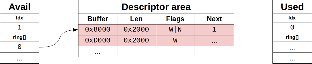
Figure 3: Device sees chained buffers
Used ring: When the device is done with the data
The device employs the used ring to return the used (read or written) buffers to the driver. As the avail ring, it has the flags and idx members. They have the same layout and serve the same purpose, although the notification flag is now called
VIRTQ_USED_F_NO_NOTIFY.
设备使用使用过的环将使用过的(读或写)缓冲区返回给驱动。与avail环一样,它也有flags和idx成员。它们具有相同的布局和相同的目的,尽管通知标志现在被称为VIRTQ_USED_F_NO_NOTIFY。
After them, it maintains an array of used descriptors. In this array, the device returns not only the descriptor index but also the used length in case of writing.
2
3
4
5
6
7
8
9
10
11
12
le16 flags;
le16 idx;
struct virtq_used_elem ring[ /* Queue Size */];
};
struct virtq_used_elem {
/* Index of start of used descriptor chain. */
le32 id;
/* Total length of the descriptor chain which was used (written to) */
le32 len;
};Listing: Used virtqueue layout
在它们之后,它维护一个已使用的描述符数组。在这个数组中,设备不仅返回描述符的索引,而且在写入的情况下返回已使用的长度。
In case of returning a chain of descriptors, only the id of the head of the chain is returned, and the total written length through all descriptors, not increasing it when data is read. The descriptor table is not touched at all, it is read-only for the device. This is step 5 in the “Process to make a buffer as used” diagram.
在返回描述符链的情况下,只返回链头的id,以及通过所有描述符的总写入长度,在读取数据时不增加它。描述符表完全不被触及,它对设备来说是只读的。这是 “制作使用的缓冲区的过程 “图中的第5步。
For example, if the device uses the chain of descriptors exposed in the Chained descriptors version:
例如,如果设备使用链式描述符版本中暴露的链式描述符:
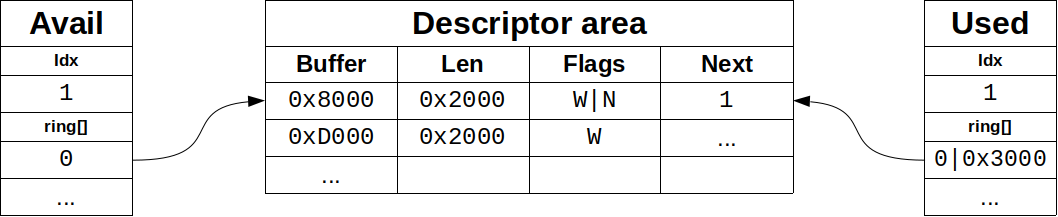
Figure 4: Device returns buffer chain
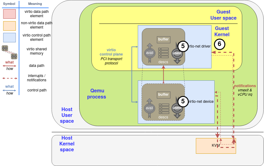
Diagram: Process to mark a buffer as used
Lastly, the device will notify the driver if it sees that the driver wants to be notified, using the used queue flags to know it (step 6).
最后,如果设备看到驱动想被通知,它将通知驱动,使用使用的队列标志来知道它(步骤6)。
Indirect descriptors: supplying a lot of data to the device
Indirect descriptors are a way to dispatch a larger number of descriptors in a batch, increasing the ring capacity. The driver stores a table of indirect descriptors (the same layout as the regular descriptors) anywhere in memory, and inserts a descriptor in the virtqueue with the flag
VIRTQ_DESC_F_INDIRECT (0x4)set. The descriptor’s address and length correspond to the indirect table’s ones.
间接描述符是一种在一个批次中调度更多描述符的方法,增加了环的容量。驱动程序在内存的任何地方存储一个间接描述符表(与普通描述符的布局相同),并在virtqueue中插入一个描述符,并设置标志VIRTQ_DESC_F_INDIRECT(0x4)。该描述符的地址和长度对应于间接表的长度。
If we want to add the chain described in section Chained descriptors to an indirect table, the driver first allocates the memory region of 2 entries (32 bytes) to hold the latter (step 2 in the diagram after allocate the buffers in the step 1):
Buffer Len Flags Next 0x8000 0x2000 W|N 1 0xD000 0x2000 W … Figure 4: Indirect table for indirect descriptors
如果我们想在一个间接表上添加链式描述符,驱动程序首先分配2个条目(32字节)的内存区域来容纳后者(图中的第2步,在第1步中分配了缓冲区之后)。
Let’s suppose it has been allocated on memory position
0x2000, and it is the first descriptor made available. As usual, the first step is to include it in the Descriptor area (step 3 in the diagram), so it would look like:
Descriptor Area Buffer Len Flags Next 0x2000 32 I … Figure 5: Add indirect table to Descriptor area
让我们假设它被分配在内存位置0x2000,并且是第一个可用的描述符。像往常一样,第一步是把它纳入描述符区域(图中的第3步),所以它看起来像。
After that, the steps are the same as with regular descriptors: The driver adds the index of the descriptor marked with the flag in the descriptor area to the avail ring (#0 in this case, step 4 in the diagram), and notify the device as usual (step 5).
之后,步骤与普通描述符相同。驱动程序将描述符区域中标有标志的描述符的索引添加到利用环中(本例中为#0,图中第4步),并像往常一样通知设备(第5步)。
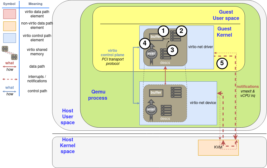
Diagram: Driver make available indirect descriptors
For the device to use its data, and would use the same memory addresses to return its
0x3000bytes (all0x8000-0x9FFFand0xD000-0xDFFF) (Step 6 and 7, same as with regular descriptors). Once used by the device, the driver can release the indirect memory or do whatever it wants with it, as it could do with any regular buffer.
对于设备使用其数据,并将使用相同的内存地址来返回其0x3000字节(所有0x8000-0x9FFF和0xD000-0xDFFF)(步骤6和7,与常规描述符相同)。一旦被设备使用,驱动程序可以释放间接内存或对其做任何事情,就像它可以对任何常规缓冲区做的那样。

Diagram: Device mark the indirect descriptor as used
Descriptors with
INDIRECTflag cannot haveNEXTorWRITEflags set, so you cannot chain indirect descriptors in the descriptor table, and the indirect table can contain at maximum the same number of descriptors as the descriptor table.
带有INDIRECT标志的描述符不能设置NEXT或WRITE标志,所以不能在描述符表中连锁间接描述符,间接表最多可以包含与描述符表相同数量的描述符。
Notifications. Learning the “do not disturb” mode
In many systems used and available buffer notifications involve significant overhead. To mitigate it, each virtring maintains a flag to indicate when it wants to be notified. Remember that the driver’s one is read-only by the device, and the device’s one is read-only by the driver.
在许多系统中,使用的和可用的缓冲区通知涉及大量的开销。为了减轻它,每个virtring都维护着一个标志,以表明它什么时候想被通知。记住,驱动的那个是设备只读的,而设备的那个是驱动只读的。
We already know all of this, and its use is pretty straightforward. The only thing you need to take care of is the asynchronous nature of this method: The side of the communication that disables or enables it can’t be sure that the other end is going to know the change, so you can miss notifications or to have more than expected.
我们已经知道了这些,它的使用是非常直接的。你唯一需要注意的是这个方法的异步性。通信中禁用或启用它的一方不能确定另一端是否会知道这个变化,所以你可能会错过通知或要比预期的多。
A more effective way of notifications toggle is enabled if the
VIRTIO_F_EVENT_IDXfeature bit is negotiated by device and driver: Instead of disable them in a binary fashion, driver and device can specify how far the other can progress before a notification is required using an specific descriptor id. This id is advertised using a extra le16 member at the end of the structure, so they grow like this:
如果设备和驱动协商VIRTIO_F_EVENT_IDX特性位,就可以启用一种更有效的通知切换方式。而不是以二进制的方式禁用它们,驱动和设备可以使用一个特定的描述符id来指定对方在需要通知之前可以进展到什么程度。这个id在结构的末尾使用一个额外的le16成员进行宣传,所以它们的增长方式是这样的。
The struct layout is:
2
3
4
5
6
le16 flags; le16 flags;
le16 idx; le16 idx;
le16 ring[ /* Queue Size */ ]; struct virtq_used_elem ring[Q. size];
le16 used_event; le16 avail_event;
}; };Listing 3: Event suppression struct notification
This way, every time the driver wants to make available a buffer it needs to check the avail_event on the used ring: If driver’s idx field was equal to avail_event, it’s time to send a notification, ignoring the lower bit of used ring flags member (
VIRTQ_USED_F_NO_NOTIFY).
这样一来,每次驱动程序想要提供一个缓冲区时,它需要检查已用环上的avail_event。如果驱动的idx字段等于avail_event,那么就是发送通知的时候了,忽略已用环标志成员的低位(VIRTQ_USED_F_NO_NOTIFY)。
Similarly, if
VIRTIO_F_EVENT_IDXhas been negotiated, the device will check used_event to know if it needs to send a notification or not. This can be very effective for maintaining a virtqueue of buffers for the device to write, like in the virtio-net device receive queue.
同样,如果VIRTIO_F_EVENT_IDX已经协商好了,设备将检查used_event以知道它是否需要发送通知。这对于维护一个供设备写入的缓冲区的虚拟队列非常有效,就像在virtio-net设备接收队列中一样。
In our next post, we’re going to wrap up and take a look at a number of optimizations on top of both ring layouts which depend on the communication/device type or how each part is implemented.
在我们的下一篇文章中,我们将总结并看看在这两个环形布局之上的一些优化,这些优化取决于通信/设备类型或每个部分的实现方式。